OUTER REAR VIEW MIRROR REMOVAL

-
PRECAUTION (w/ Navigation System for HDD)
Note
After the power switch is turned off, the display and navigation module display (HDD navigation system) records various types of memory and settings. As a result, after turning the power switch off, make sure to wait at least 60 seconds before disconnecting the cable from the negative (-) battery terminal.
-
REMOVE REAR NO. 2 FLOOR BOARD
-

Disengage the 2 guides <A> as shown in the illustration.
-
Disengage the 3 guides <B> and remove the rear No. 2 floor board.
-
-
REMOVE REAR DECK FLOOR BOX
-
Remove the rear deck floor box.
-
-
REMOVE REAR NO. 3 FLOOR BOARD
-

Disengage the 2 guides and remove the rear No. 3 floor board.
-
-
DISCONNECT CABLE FROM NEGATIVE BATTERY TERMINAL
Note
When disconnecting the cable, some systems need to be initialized after the cable is reconnected Click here.
-
REMOVE FRONT DOOR INSIDE HANDLE BEZEL PLUG
-
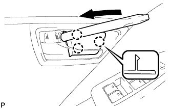
Using a moulding remover, disengage the 3 claws and remove the front door inside handle bezel plug.
-
-
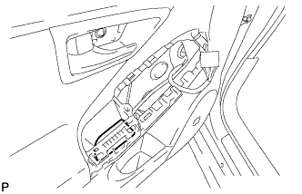
REMOVE ASSIST GRIP COVER
-
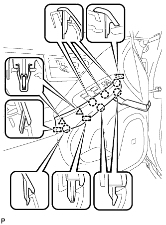
Using a moulding remover, disengage the 6 claws, 2 clips and 3 guides, and remove the assist grip cover.
-
-
REMOVE POWER WINDOW REGULATOR MASTER SWITCH ASSEMBLY WITH FRONT DOOR ARMREST BASE PANEL
-
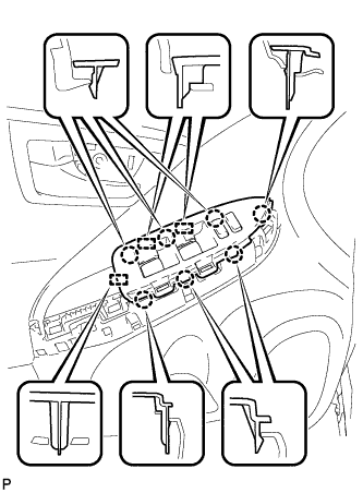
Disengage the 7 claws and 3 guides.
-
Disconnect the connector and remove the power window regulator master switch assembly with front door armrest base panel.
-
-
REMOVE POWER WINDOW REGULATOR SWITCH ASSEMBLY WITH FRONT DOOR ARMREST BASE PANEL
-
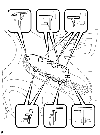
Disengage the 7 claws and 3 guides.
-
Disconnect the connector and remove the power window regulator switch assembly with front door armrest base panel.
-
-
REMOVE DOOR ARMREST COVER
-
Remove the door armrest cover.
-
-
REMOVE COURTESY LIGHT ASSEMBLY
-
Using a moulding remover, disengage the claw.
-
Disconnect the connector and remove the courtesy light assembly.
-
-
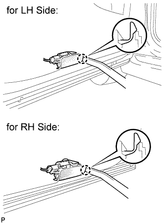
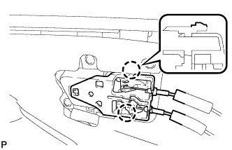
REMOVE FRONT DOOR INSIDE HANDLE SUB-ASSEMBLY
-
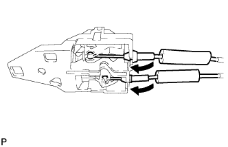
Disconnect the front door lock remote control cable and front door inside locking cable, and remove the front door inside handle sub-assembly.
-
-
REMOVE FRONT DOOR TRIM BOARD SUB-ASSEMBLY
-
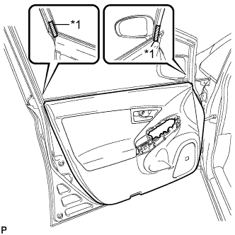
Text in Illustration *1 Protective Tape Put protective tape around the front door panel.
-
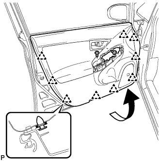
Remove the 2 screws.
-
Using a clip remover, disengage the 9 clips.
-
Pull out the front door trim board sub-assembly in the direction indicated by the arrow in the illustration.
-
Raise the front door trim board sub-assembly and remove the front door trim board sub-assembly together with the front door inner glass weatherstrip.
-
Disengage the 2 claws and disconnect the front door inside handle sub-assembly.
-
-
REMOVE OUTER MIRROR PROTECTOR
-
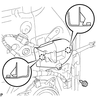
Remove the screw.
-
Disengage the 2 claws and remove the outer mirror protector.
-
-
REMOVE OUTER MIRROR INSTALL HOLE COVER
-
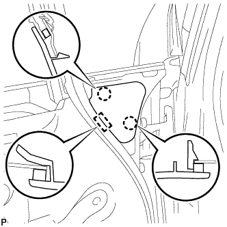
Disengage the 2 claws and guide, remove the outer mirror install hole cover.
-
-
REMOVE OUTER REAR VIEW MIRROR ASSEMBLY
-

Disconnect the connector.
-
Remove the 3 bolts.
-
Disengage the clip and remove the outer rear view mirror assembly.
-
-
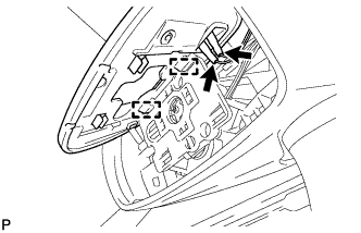
REMOVE OUTER MIRROR
-
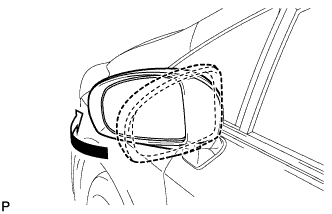
Push the outside part of the outer mirror assembly and tilt it as show in the illustration.
-
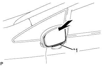
Text in Illustration *1 Protruding Part Push the upper part of the mirror surface and tilt it.
-
Apply protective tape as shown in the illustration.
-
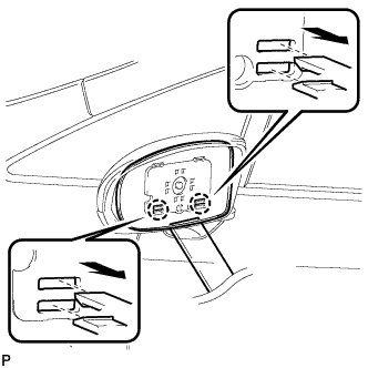
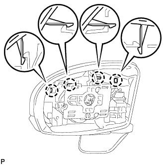
Using a moulding remover, disengage the 2 claws at the lower part of the outer rear view mirror, and separate the outer rear view mirror glass.
-
w/o Mirror Heater:
-
Disengage the 2 guides at the upper part of the outer mirror
-
Remove the outer mirror.
-
-
w/ Mirror Heater:
-
Disengage the 2 guides at the upper part of the outer mirror.
-
Disconnect the 2 connectors and remove the outer mirror.
-
-
-
REMOVE OUTER MIRROR COVER
-
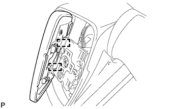
Disengage the 4 claws.
-
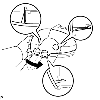
Disengage the 3 claws and remove the outer mirror cover as shown in the illustration.
-