POWER MIRROR CONTROL SYSTEM Mirror Heater does not Operate with Rear Defogger Switch
DESCRIPTION
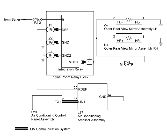
When the rear window defogger switch on the air conditioning control panel assembly is pressed, the operation signal is transmitted to the air conditioning amplifier assembly through a LIN communication line. When the air conditioning amplifier assembly receives the signal, it turns on the integration relay to operate the mirror heater.
WIRING DIAGRAM
INSPECTION PROCEDURE
Note
Inspect the fuses for circuits related to this system before performing the following inspection procedure.
PROCEDURE
-
PERFORM ACTIVE TEST USING INTELLIGENT TESTER
-
Connect the intelligent tester to the DLC3.
-
Turn the power switch on (IG).
-
Turn the intelligent tester on.
-
Enter the following menus: Body /Air Conditioner / Active Test.
-
Perform an Active Test according to the display on the intelligent tester.
Air Conditioner Tester Display Test Part Control Range Diagnostic Note Mirror Heater Relay Mirror heater ON / OFF - Result Result Proceed to Mirror heater operation on both mirrors is not normal A Mirror heater operation on RH side mirror is not normal B Mirror heater operation on LH side mirror is not normal C
B 
CHECK OUTER REAR VIEW MIRROR ASSEMBLY RH Click here
C
CHECK OUTER REAR VIEW MIRROR ASSEMBLY LH Click here
A 
-
-
CHECK DEFOGGER SYSTEM
-
Check the rear window defogger operation.
OK The rear window defogger operated normally.
NG 
GO TO WINDOW DEFOGGER SYSTEM Click here
OK
-
-
CHECK HARNESS AND CONNECTOR (INTEGRATION RELAY - BODY GROUND)
-
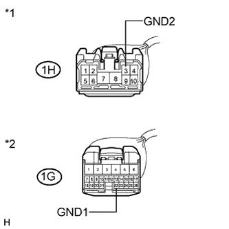
Text in Illustration *1 Front view of wire harness connector
(to Integration Relay)
*2 Front view of wire harness connector
(to Integration Relay)
Disconnect the integration relay connector.
-
Measure the resistance according to the value(s) in the table below.
Standard Resistance Tester Connection Condition Specified Condition 1H-3 (GND2) - Body ground Always Below 1 Ω 1G-22 (GND1) - Body ground Always Below 1 Ω
NG
REPAIR OR REPLACE HARNESS OR CONNECTOR
OK
-
-
CHECK HARNESS AND CONNECTOR (OUTER REAR VIEW MIRROR ASSEMBLY RH - INTEGRATION RELAY)
-
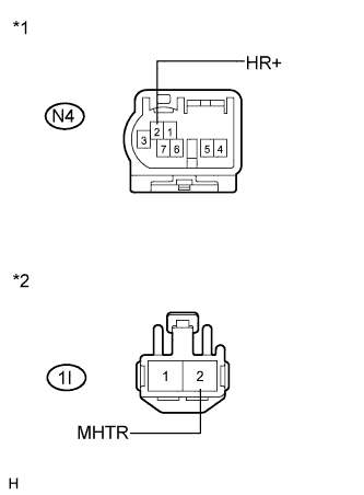
Text in Illustration *1 Front view of wire harness connector
(to Outer Rear View Mirror Assembly RH)
*2 Front view of wire harness connector
(to Integration Relay)
Disconnect the integration relay connector.
-
Disconnect the outer rear view mirror assembly RH connector.
-
Measure the resistance according to the value(s) in the table below.
Standard Resistance Tester Connection Condition Specified Condition 1I-2 (MHTR) - N4-2 (HR+) Always Below 1 Ω 1I-2 (MHTR) - Body ground Always 10 kΩ or higher
NG
REPAIR OR REPLACE HARNESS OR CONNECTOR
OK
-
-
CHECK HARNESS AND CONNECTOR (OUTER REAR VIEW MIRROR ASSEMBLY LH - INTEGRATION RELAY)
-
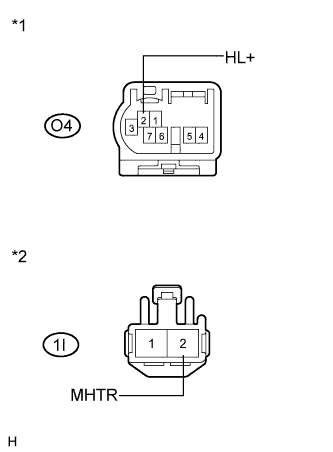
Text in Illustration *1 Front view of wire harness connector
(to Outer Rear View Mirror Assembly LH)
*2 Front view of wire harness connector
(to Integration Relay)
Disconnect the integration relay connector.
-
Disconnect the outer rear view mirror assembly LH connector.
-
Measure the resistance according to the value(s) in the table below.
Standard Resistance Tester Connection Condition Specified Condition 1I-2 (MHTR) - O4-2 (HL+) Always Below 1 Ω 1I-2 (MHTR) - Body ground Always 10 kΩ or higher
NG
REPAIR OR REPLACE HARNESS OR CONNECTOR
OK
-
-
REPLACE INTEGRATION NO.1 RELAY
-
Replace the integration relay Click here.
OK
-
-
CHECK REAR WINDOW DEFOGGER AND MIRROR HEATER
-
Check the mirror heater system.
OK Mirror heater system is normal.
NG
REPLACE AIR CONDITIONING AMPLIFIER ASSEMBLY Click here
OK 
END (INTEGRATION RELAY WAS DEFECTIVE)
-
-
CHECK OUTER REAR VIEW MIRROR ASSEMBLY RH
-
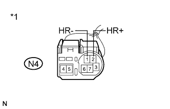
Text in Illustration *1 Component without harness connected
(Outer Rear View Mirror Assembly RH)
Remove the outer rear view mirror assembly RH Click here.
-
Measure the resistance according to the value(s) in the table below.
Standard Resistance Tester Connection Condition Specified Condition N4-2 (HR+) - N4-1 (HR-) 25°C (77°F) 7.6 to 11.4 Ω
NG
REPLACE OUTER REAR VIEW MIRROR ASSEMBLY RH Click here
OK
REPAIR OR REPLACE HARNESS OR CONNECTOR (INTEGRATION RELAY - OUTER REAR VIEW MIRROR ASSEMBLY RH)
-
-
CHECK OUTER REAR VIEW MIRROR ASSEMBLY LH
-
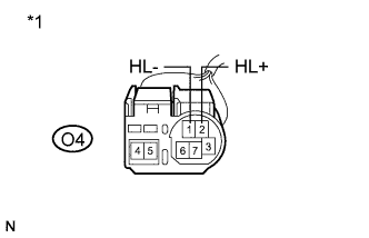
Text in Illustration *1 Component without harness connected
(Outer Rear View Mirror Assembly LH)
Remove the outer rear view mirror assembly LH Click here.
-
Measure the resistance according to the value(s) in the table below.
Standard Resistance Tester Connection Condition Specified Condition O4-2 (HL+) - O4-1 (HL-) 25°C (77°F) 7.6 to 11.4 Ω
NG
REPLACE OUTER REAR VIEW MIRROR ASSEMBLY LH Click here
OK
REPAIR OR REPLACE HARNESS OR CONNECTOR (INTEGRATION RELAY - OUTER REAR VIEW MIRROR ASSEMBLY LH)
-