FUEL LID LOCK CONTROL CABLE ASSEMBLY INSTALLATION

-
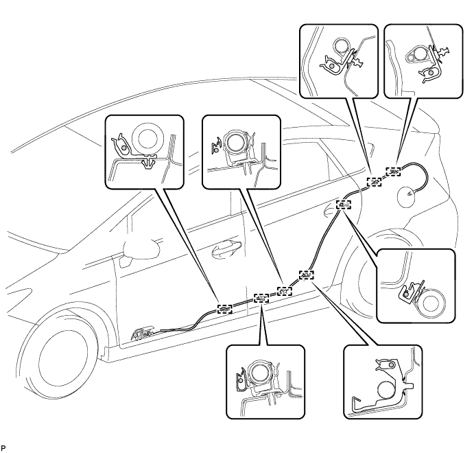
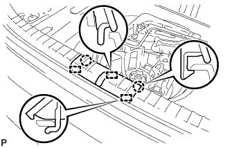
INSTALL FUEL LID LOCK CONTROL CABLE SUB-ASSEMBLY (for LHD)
-
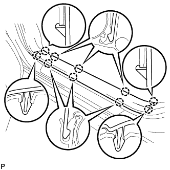
Engage the 7 clamps.
-
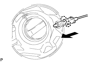
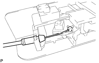
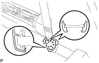
Engage the 2 claws and connect the fuel lid lock control cable sub-assembly.
-
-
INSTALL FUEL LID LOCK OPEN LEVER SUB-ASSEMBLY (for LHD)
-
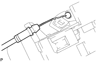
Connect the fuel lid lock control cable sub-assembly.
-
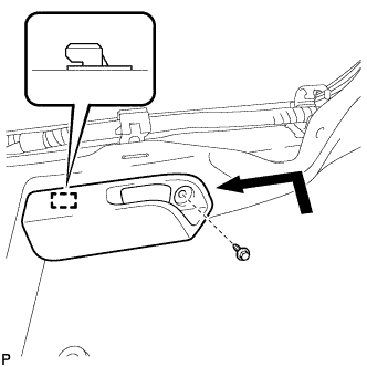
Engage the guide and install the fuel lid lock open lever sub-assembly with the screw.
- Torque:
- 5.5 N*m { 56 kgf*cm, 49 in.*lbf }
-
-
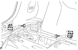
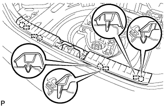
INSTALL FUEL LID LOCK CONTROL CABLE SUB-ASSEMBLY (for RHD)
-
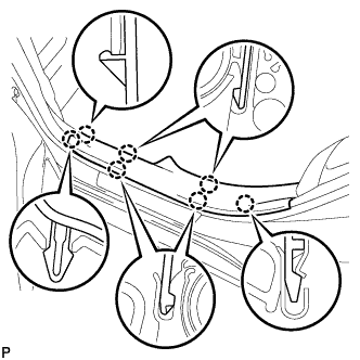
Engage the 12 clamps.

-
Engage the 2 claws and connect the fuel lid lock control cable sub-assembly.
-
-
INSTALL FUEL LID LOCK OPEN LEVER SUB-ASSEMBLY (for RHD)
-
Connect the fuel lid lock control cable sub-assembly.
-
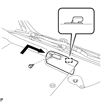
Engage the guide and install the fuel lid lock open lever sub-assembly with the screw.
- Torque:
- 5.5 N*m { 56 kgf*cm, 49 in.*lbf }
-
-
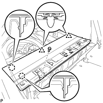
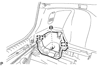
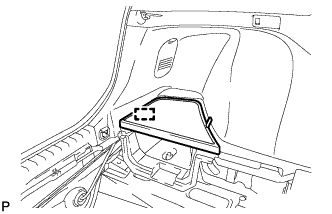
INSTALL DECK TRIM SIDE PANEL ASSEMBLY LH
-
Connect the connector.
-
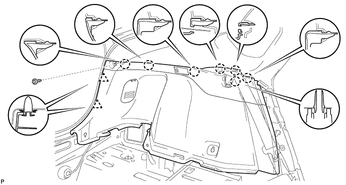
Engage the 7 claws and 2 clips.
-
Install the deck trim side panel assembly LH with the screw.
-
-
INSTALL TONNEAU COVER HOLDER CAP
-
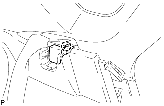
Engage the claw to install the tonneau cover holder cap.
-
-
INSTALL LUGGAGE HOLD BELT STRIKER ASSEMBLY
-
Engage the 2 guides.
-
Install the 2 luggage hold belt striker assemblies with the 2 bolts.
-
-
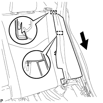
INSTALL REAR DECK TRIM COVER
-
Engage the 4 claws and 4 guides to install the rear deck trim cover.
-
-
INSTALL DECK TRIM SERVICE HOLE COVER
-
Engage the 3 guides.
-
Engage the 2 claws to install the deck trim service hole cover.
-
-
INSTALL REAR NO. 1 FLOOR BOARD
-
Engage the 2 claws and 2 clips.
-
Install the rear No. 1 floor board with the bolt.
-
-
INSTALL REAR NO. 2 FLOOR BOARD SUB-ASSEMBLY
-

Engage the claw and 2 clips to install the rear No. 2 floor board sub-assembly.
-
-
INSTALL REAR NO. 1 FLOOR BOARD SUB-ASSEMBLY
-
Engage the 2 claws and 2 clips to install the rear No. 1 floor board sub-assembly.
-
-
INSTALL DECK FLOOR BOX LH
-
Engage the 2 guides.
-
Install the deck floor box LH with the clip.
-
-
INSTALL REAR NO. 4 FLOOR BOARD
-
Engage the guide to install the rear No. 4 floor board.
-
-
INSTALL TONNEAU COVER ASSEMBLY (w/ Tonneau Cover)
-
Install the tonneau cover assembly.
-
-
INSTALL REAR SIDE SEATBACK ASSEMBLY LH
-
Engage the 2 guides as shown in the illustration.
-
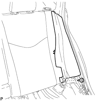
Install the rear side seatback assembly LH with the bolt.
- Torque:
- 18 N*m { 184 kgf*cm, 13 ft.*lbf }
-
-
INSTALL REAR SEAT CUSHION ASSEMBLY
-
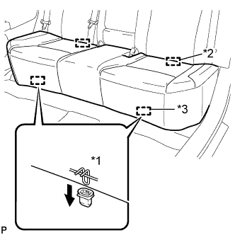
Text in Illustration *1 100 mm (3.94 in.) or less *2 Guide *3 Hook Engage the 2 guides of the seat cushion to the seatback.
-
Engage the 2 front hooks of the seat cushion to the vehicle body.
Note
When installing the seat cushion, make sure that the seat belt buckle is not under the seat cushion.
Tech Tips
Confirm that the seat cushion is firmly installed.
-
-
INSTALL CENTER PILLAR LOWER GARNISH LH (for LHD)
-
Engage the 2 claws and 2 clips to install the center pillar lower garnish LH.
-
-
CONNECT FRONT SEAT OUTER BELT ASSEMBLY LH (for LHD)
-
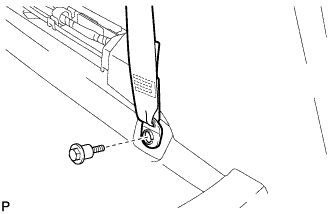
Install the floor end of the front seat outer belt assembly with the bolt.
- Torque:
- 42 N*m { 428 kgf*cm, 31 ft.*lbf }
-
Check if the ELR locks.
Note
The check should be performed with the outer belt assembly installed.
-
With the belt assembly installed, check that the belt locks when it is pulled out quickly.
-
-
-
INSTALL LAP BELT OUTER ANCHOR COVER LH (for LHD)
-
Engage the 3 claws to install the lap belt outer anchor cover.
-
-
CONNECT REAR DOOR OPENING TRIM WEATHERSTRIP LH (for LHD)
-
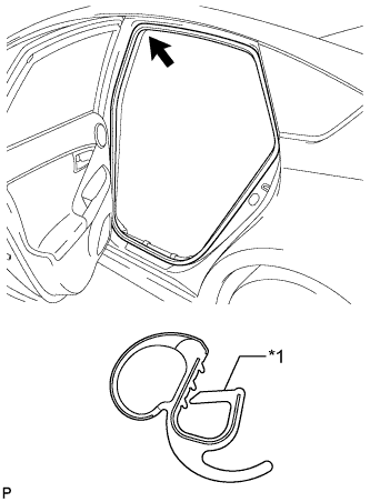
Text in Illustration *1 Alignment Mark (Red) Align the alignment mark (Red) on the weatherstrip with the protruding portion on the body indicated by the arrow in the illustration, and install the rear door opening trim weatherstrip LH.
Note
After installation, check that the corners fit correctly.
-
-
INSTALL REAR DOOR SCUFF PLATE LH (for LHD)
-
Engage the 7 claws to install the rear door scuff plate LH.
-
-
INSTALL FRONT DOOR SCUFF PLATE LH (for LHD)
-
Engage the 10 claws to install the front door scuff plate LH.
-
-
INSTALL FRONT SEAT ASSEMBLY LH (for LHD)
Tech Tips
Refer to the procedure from Install Front Seat Assembly LH Click here
-
INSTALL CENTER PILLAR LOWER GARNISH RH (for RHD)
Tech Tips
Use the same procedure for the RH side and LH side.
-
CONNECT FRONT SEAT OUTER BELT ASSEMBLY RH (for RHD)
Tech Tips
Use the same procedure for the RH side and LH side.
-
INSTALL LAP BELT OUTER ANCHOR COVER RH (for RHD)
Tech Tips
Use the same procedure for the RH side and LH side.
-
CONNECT REAR DOOR OPENING TRIM WEATHERSTRIP RH (for RHD)
Tech Tips
Use the same procedure for the RH side and LH side.
-
INSPECT REAR DOOR SCUFF PLATE RH (for RHD)
Tech Tips
Use the same procedure for the RH side and LH side.
-
INSTALL FRONT DOOR SCUFF PLATE RH (for RHD)
Tech Tips
Use the same procedure for the RH side and LH side.
-
INSTALL FRONT SEAT ASSEMBLY RH (for RHD)
Tech Tips
Use the same procedure for the RH side and LH side.
-
CONNECT CABLE TO NEGATIVE BATTERY TERMINAL
Note
When disconnecting the cable, some systems need to be initialized after the cable is reconnected Click here.
-
INSTALL REAR NO. 3 FLOOR BOARD
-

Engage the 2 guides to install the rear No. 3 floor board.
-
-
INSTALL REAR DECK FLOOR BOX
-
Install the rear deck floor box.
-
-
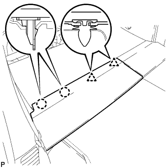
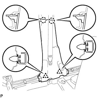
INSTALL REAR NO. 2 FLOOR BOARD
-

Engage the 3 guides <A>.
-
Engage the 2 guides <B> and install the rear No. 2 floor board as shown in the illustration.
-
-
INSPECT SRS WARNING LIGHT