OUTER MIRROR SWITCH INSPECTION

-
INSPECT OUTER MIRROR SWITCH
-
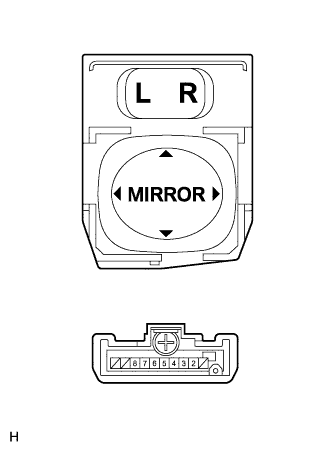
Inspect the outer mirror switch.
-
Measure the resistance according to the value(s) in the table below when the switch is operated.
Tech Tips
Select "L" on the left/right adjustment switch.
Tester Connection Switch Condition Specified Condition 4 - 8 Up Below 1 Ω 6 - 7 4 - 7 Down 6 - 8 5 - 8 Left 6 - 7 5 - 7 Right 6 - 8 Tech Tips
Select "R" on the left/right adjustment switch.
Tester Connection Switch Condition Specified Condition 3 - 8 Up Below 1 Ω 6 - 7 3 - 7 Down 6 - 8 2 - 8 Left 6 - 7 2 - 7 Right 6 - 8 If the result is not as specified, replace the outer mirror switch assembly.
-
-