FRONT DOOR ADJUSTMENT

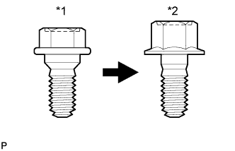
| *1 | Centering Bolt |
| *2 | Standard Bolt |
CAUTION:
Before adjusting the door positions of vehicles equipped with side and curtain shield airbags, be sure to disconnect the battery. After adjustment, check that the SRS warning light is operating normally and there are no SRS DTCs output.
Tech Tips
-
Use the same procedure for the RH side and LH side.
-
The following procedure is for the LH side.
-
Centering bolts are used to mount the door hinge to the vehicle body and door. The door cannot be adjusted with the centering bolts installed on it. Substitute the centering bolts with standard bolts when making adjustments.
-
Specified torque for standard bolts is shown in the standard bolt chart Click here.
-
INSPECT FRONT DOOR
-
Check that the clearance measurements of areas *1 through *11 are within each standard range.
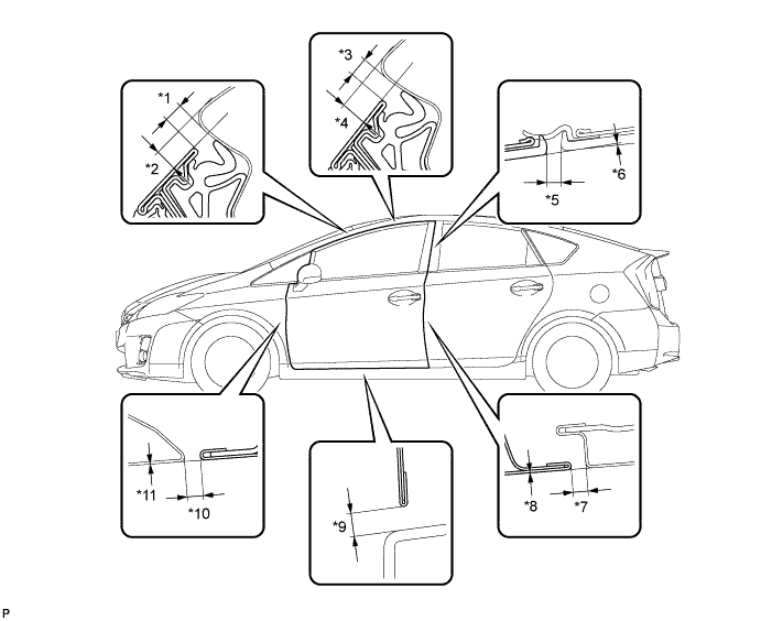
Standard Clearance Area Measurement Area Measurement *1 3.57 to 6.57 mm (0.141 to 0.259 in.) *2 4.57 to 7.57 mm (0.180 to 0.298 in.) *3 3.57 to 6.57 mm (0.141 to 0.259 in.) *4 5.17 to 8.17 mm (0.204 to 0.322 in.) *5 2.8 to 5.8 mm (0.110 to 0.228 in.) *6 -1.3 to 1.7 mm (-0.0512 to 0.0669 in.) *7 2.7 to 5.7 mm (0.106 to 0.1224 in.) *8 -1.5 to 1.5 mm (-0.0591 to 0.0591 in.) *9 4.15 to 7.15 mm (0.163 to 0.282 in.) *10 2.8 to 5.8 mm (0.110 to 0.228 in.) *11 -1.5 to 1.5 mm (-0.0591 to 0.0591 in.) - -
-
-
REMOVE REAR NO. 2 FLOOR BOARD
-

Disengage the 2 guides <A> as shown in the illustration.
-
Disengage the 3 guides <B> and remove the rear No. 2 floor board.
-
-
REMOVE REAR DECK FLOOR BOX
-
Remove the rear deck floor box.
-
-
REMOVE REAR NO. 3 FLOOR BOARD
-

Disengage the 2 guides and remove the rear No. 3 floor board.
-
-
PRECAUTION (w/ Navigation System for HDD)
Note
After the power switch is turned off, the display and navigation module display (HDD navigation system) records various types of memory and settings. As a result, after turning the power switch off, make sure to wait at least 60 seconds before disconnecting the cable from the negative (-) battery terminal.
-
DISCONNECT CABLE FROM NEGATIVE BATTERY TERMINAL
CAUTION:
Wait at least 90 seconds after disconnecting the cable from the negative (-) battery terminal to disable the SRS system.
Note
When disconnecting the cable, some systems need to be initialized after the cable is reconnected Click here.
-
ADJUST FRONT DOOR
-
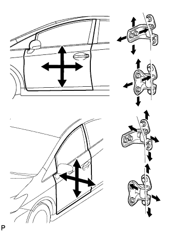
Using SST, loosen the hinge bolts on the vehicle body and adjust the door position.
- SST
- 09812-00010
-
Tighten the hinge bolts on the vehicle body after the adjustment.
- Torque:
- 26 N*m { 265 kgf*cm, 19 ft.*lbf }
-
Loosen the hinge bolts on the door and adjust the door position.
-
Tighten the hinge bolts on the door after the adjustment.
- Torque:
- 26 N*m { 265 kgf*cm, 19 ft.*lbf }
-
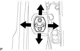
Using a T40 "TORX" socket wrench, slightly loosen the striker mounting screws.
-
Using a brass bar and a hammer, hit the striker to adjust its position.
-
Using a T40 "TORX" socket wrench, tighten the striker mounting screws after the adjustment.
- Torque:
- 23 N*m { 235 kgf*cm, 17 ft.*lbf }
-
-
CONNECT CABLE TO NEGATIVE BATTERY TERMINAL
Note
When disconnecting the cable, some systems need to be initialized after the cable is reconnected Click here.
-
INSTALL REAR NO. 3 FLOOR BOARD
-
Engage the 2 guides to install the rear No. 3 floor board.
-
-
INSTALL REAR DECK FLOOR BOX
-
Install the rear deck floor box.
-
-
INSTALL REAR NO. 2 FLOOR BOARD
-

Engage the 3 guides <A>.
-
Engage the 2 guides <B> and install the rear No. 2 floor board as shown in the illustration.
-
-
INSPECT SRS WARNING LIGHT