SLIDING ROOF HOUSING INSTALLATION

-
TEMPORARILY INSTALL REAR SLIDE ROOF PANEL SUB-ASSEMBLY
-
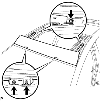
Temporarily install the rear slide roof panel sub-assembly with the 16 nuts.
Note
-
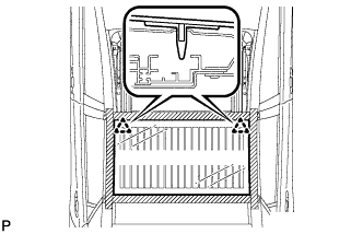
When installing the roof panel to the vehicle, first install the roof panel center front and center rear alignment bolts to the vehicle front and rear alignment bolt installation points, as shown in the illustration.
-
When installing the roof panel, be careful not to damage the vehicle.
-
Perform this step with 2 or more technicians.
-
-
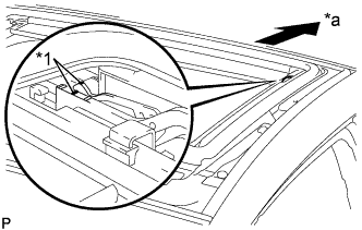
Check that the alignment bolts are firmly installed.
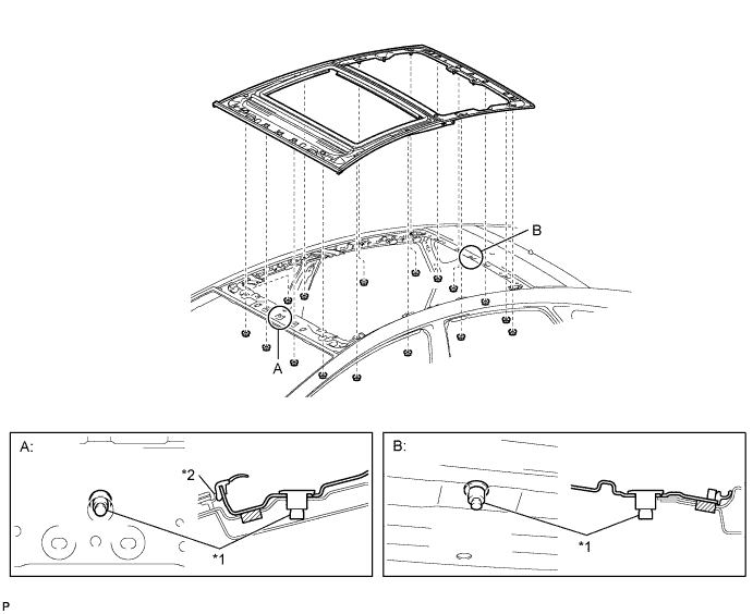
Text in Illustration *1 Alignment Bolt *2 Windshield Glass Moulding Note
-
When the bolts are not firmly installed, water leaks and malfunctions will occur.
-
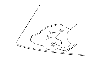
Make sure that the lip of the windshield glass moulding is not folded down.
-
-
-
FULLY TIGHTEN REAR SLIDE ROOF PANEL SUB-ASSEMBLY
-
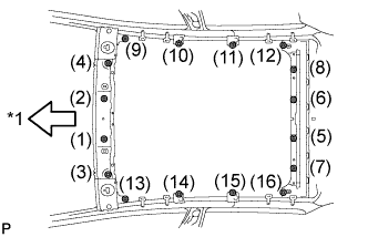
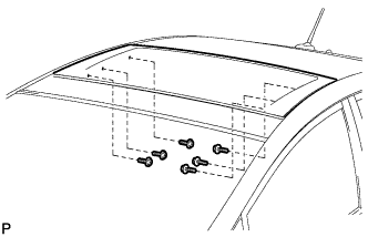
Text in Illustration *1 Front Side Fully tighten the 16 nuts to install the rear slide roof panel sub-assembly.
- Torque:
- 5.5 N*m { 56 kgf*cm, 49 in.*lbf }
Tech Tips
Tighten the nuts in the order indicated in the illustration.
-
-
CLEAN MOON ROOF GLASS ASSEMBLY
-
Clean the outer edge of the moon roof glass with a non-residue solvent.
Note
-
Do not touch the moon roof glass surface after cleaning it.
-
Be careful not to damage the glass.
-
Even if using a new moon roof glass, clean the moon roof glass with a non-residue solvent.
-
-
-
INSTALL MOON ROOF GLASS ASSEMBLY
-
Using a brush, coat the installation surface on the rear slide roof panel sub-assembly with Primer M.
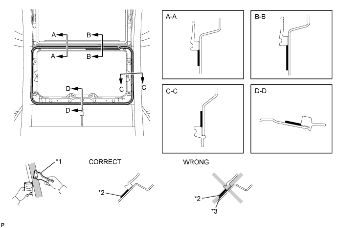
Text in Illustration *1 Brush *2 Primer M *3 Adhesive - - Note
-
Do not coat the adhesive with Primer M.
-
Do not apply too much primer.
-
Allow the primer to dry for 3 minutes or more.
-
Throw away any leftover primer.
Tech Tips
If an area other than that specified is coated by accident, wipe off the primer with a clean piece of cloth before it dries.
-
-
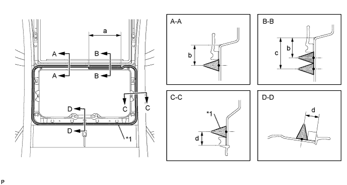
Using a brush or a sponge, coat the application area of the adhesive with Primer G.
Text in Illustration *1 Primer G Standard Area Dimension a 7.0 mm (0.276 in.) b 8.0 mm (0.315 in.) c 16.0 mm (0.630 in.) Note
-
Do not apply too much primer.
-
Allow the primer to dry for 3 minutes or more.
-
Throw away any leftover primer.
Tech Tips
If an area other than that specified is coated by accident, wipe off the primer with a clean piece of cloth before it dries.
-
-
Apply adhesive to the rear sliding roof rail sub-assembly.
Adhesive Toyota Genuine Windshield Glass Adhesive or equivalent
-
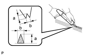
Cut off the tip of the cartridge nozzle as shown in the illustration.
Standard Dimension Area Dimension a 12.0 mm (0.472 in.) b 8.0 mm (0.315 in.) Tech Tips
After cutting off the tip, use all the adhesive within the time described in the table below.
Usage Time Frame Temperature Usage Time Frame 35°C (95°F) 15 minutes 20°C (68°F) 1 hour and 40 minutes 5°C (41°F) 8 hours -
Load the sealer gun with cartridge.
-
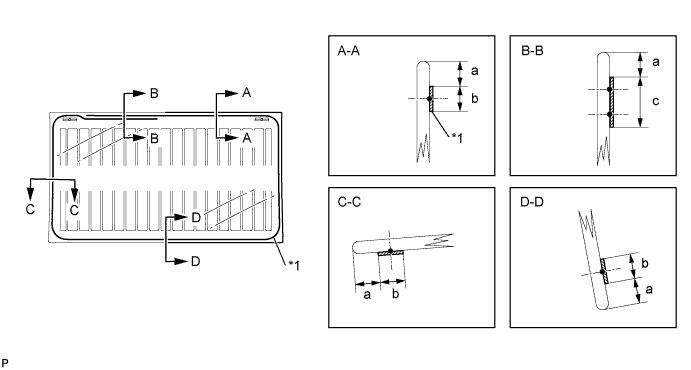
Apply adhesive to the rear sliding roof rail sub-assembly as shown in the illustration.
Text in Illustration *1 Adhesive Standard Dimension Area Dimension a 100 mm (3.94 in.) b 14.0 mm (0.551 in.) c 22.0 mm (0.866 in.) d 8.0 mm (0.315 in.)
-
-
Install the moon roof glass assembly.
-
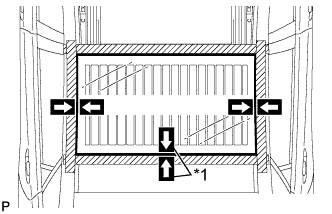
Text in Illustration *1 Matchmark Position the moon roof glass assembly so that the matchmarks are aligned, and press it in gently along the rim (when glass without a clip is used).
-
Lightly press the moon roof glass assembly to ensure that the moon roof glass assembly is securely fit to the vehicle body (when glass without a clip is used).
Tech Tips
Press the moon roof glass assembly with a force of 98 N (10 kgf, 22.0 lbf) or more.
-
Using suction cups, engage the 2 clips to install the moon roof glass assembly.
Note
-
Check that the clips are attached to the vehicle body correctly.
-
Check the clearance between the vehicle body and moon roof glass assembly.
-
-
Lightly press the front surface of the moon roof glass assembly to ensure that the moon roof glass assembly is securely fit to the vehicle body.
Tech Tips
Press the moon roof glass assembly with a force of 98 N (10 kgf, 22.0 lbf) or more.
-
Inspect the position of the moon roof glass assembly so that the measurements are within the standard values shown in the illustration.
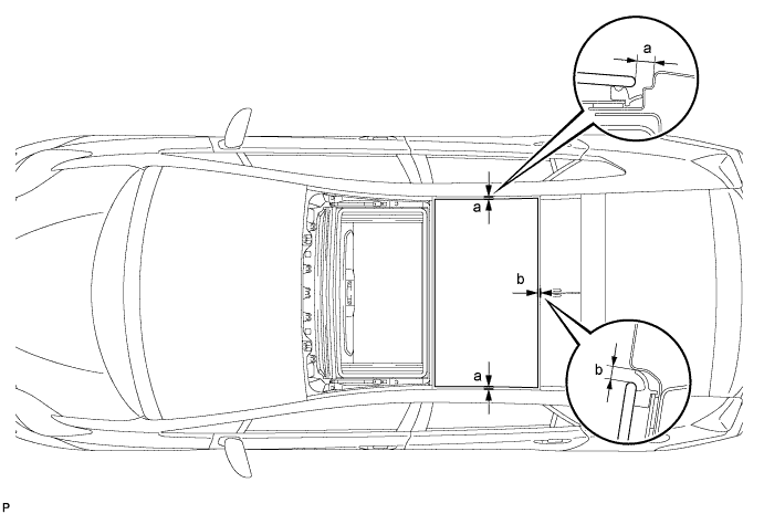
Standard Area Measurement a 7.4 mm + 2.0 mm (0.291 in. + 0.0787 in.)
7.4 mm - 2.0 mm (0.291 in. - 0.0787 in.)
b 5.0 mm + 2.0 mm (0.197 in. + 0.0787 in.)
5.0 mm - 2.0 mm (0.197 in. - 0.0787 in.)
Tech Tips
"+" represents the condition that the glass is above the panel level. "-" represents the condition that the glass is below the panel level.
-
Hold the moon roof glass assembly using protective tape until applied adhesive becomes hard.
Note
Do not drive the vehicle within the time described in the table below.
Minimum Time Temperature Minimum Time prior to Driving Vehicle 35°C (95°F) 1 hour and 30 minutes 20°C (68°F) 5 hours 5°C (41°F) 24 hours
-
-
-
INSTALL SLIDING ROOF RAIL SUB-ASSEMBLY
-
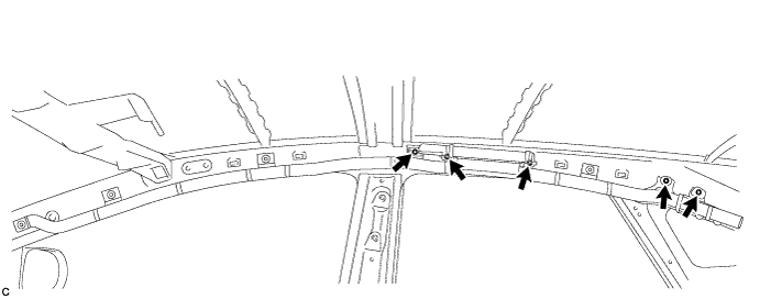
Install the sliding roof rail sub-assembly with the 12 nuts.
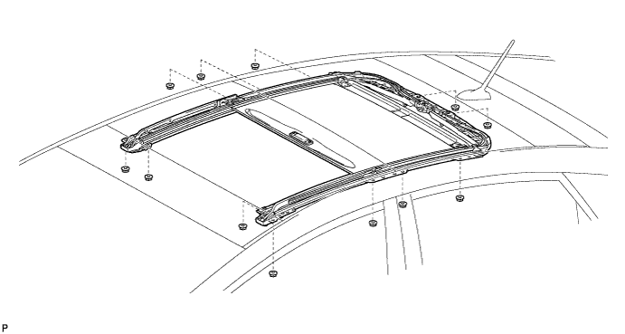
- Torque:
- 7.0 N*m { 71 kgf*cm, 62 in.*lbf }
-
Engage the clamp.
-
Connect the connector.
-
-
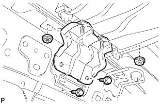
INSTALL CENTER SLIDING ROOF HOUSING MOUNTING BRACKET LH
-
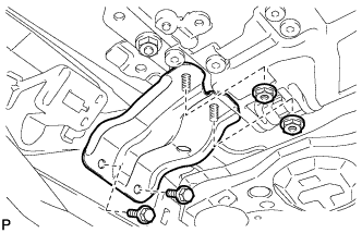
Install the center sliding roof housing mounting bracket LH with the 2 bolts and 2 nuts.
- Torque:
- Bolt
- 5.0 N*m { 51 kgf*cm, 44 in.*lbf }
- Nut
- 5.5 N*m { 56 kgf*cm, 49 in.*lbf }
-
-
INSTALL CENTER SLIDING ROOF HOUSING MOUNTING BRACKET RH
Tech Tips
Use the same procedure for the RH side and LH side.
-
INSTALL FRONT SLIDING ROOF HOUSING MOUNTING BRACKET LH
-
Install the front sliding roof housing mounting bracket LH with the 2 bolts and 2 nuts.
- Torque:
- Bolt
- 5.0 N*m { 51 kgf*cm, 44 in.*lbf }
- Nut
- 5.5 N*m { 56 kgf*cm, 49 in.*lbf }
-
-
INSTALL FRONT SLIDING ROOF HOUSING MOUNTING BRACKET RH
Tech Tips
Use the same procedure for the RH side and LH side.
-
ADJUST FULLY CLOSED POSITION
-
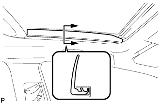
Text in Illustration *1 Matchmark *a Rear Side Using a screwdriver, slide the sliding roof drive cable to align the matchmarks.
Tech Tips
Tape the screwdriver tip before use.
-
-
INSTALL SLIDING ROOF DRIVE GEAR SUB-ASSEMBLY
-
When replacing the sliding roof drive gear sub-assembly with a new ones:
-
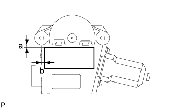
Install a new slide roof motor cushion as shown in the illustration.
Standard Area Dimension a 1.0 mm (0.0394 in.) b 1.5 mm (0.0591 in.)
-
-
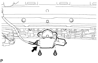
Install the sliding roof drive gear sub-assembly with the 2 bolts.
- Torque:
- 5.4 N*m { 55 kgf*cm, 48 in.*lbf }
-
-
INSTALL REAR SIDE RAIL SPACER LH
-
Engage the 2 clamps and install the rear side rail spacer LH
-
-
INSTALL REAR SIDE RAIL SPACER RH
Tech Tips
Use the same procedure for the RH side and LH side.
-
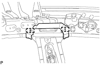
INSTALL CURTAIN SHIELD AIRBAG ASSEMBLY LH
-
Check that the power switch is off.
-
Check that the cable is disconnected from the negative (-) battery terminal.
CAUTION:
Wait at least 90 seconds after disconnecting the cable from the negative (-) battery terminal to disable the SRS system.
-
Temporarily install the curtain shield airbag assembly with the 5 hooks.
Note
Do not twist the curtain shield airbag assembly when installing it.
-
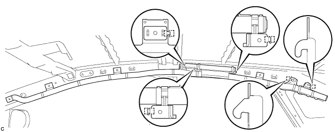
Install the curtain shield airbag assembly to the body panel with 4 new clips and 4 new spacers.
-
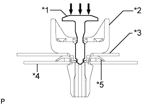
Text in Illustration *1 Pin *2 Clip *3 Airbag *4 Body *5 Spacer Install 4 new pins as shown in the illustration.
Note
Make sure that the pins of the clips are pushed in firmly.
-
-
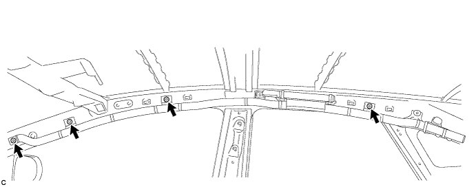
Install the 5 bolts.
- Torque:
- 9.8 N*m { 100 kgf*cm, 87 in.*lbf }
-
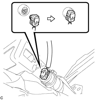
Connect the curtain shield airbag connector.
Note
When connecting any airbag connector, take care not to damage the airbag wire harness.
-
Push in the lock to install the airbag connector.
-
-
INSTALL CURTAIN SHIELD AIRBAG ASSEMBLY RH
Tech Tips
Use the same procedure for the RH side and LH side.
-
TEMPORARILY INSTALL TILT ROOF GLASS SUB-ASSEMBLY
-
Using a T20 "TORX" driver, install the tilt roof glass sub-assembly with the 6 screws.
-
-
TEMPORARILY INSTALL SLIDING ROOF GLASS SUB-ASSEMBLY
-
Using a T25 "TORX" driver, install the 6 screws.
-
-
ADJUST SLIDING ROOF GLASS
-
Adjust the sliding roof glass sub-assembly:
-
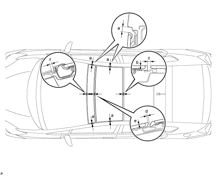
Adjust the position of the sliding roof glass sub-assembly so that the measurements are within the standard values shown in the illustration.
Standard Area Measurement a 7.4 mm + 2.0 mm (0.291 in. + 0.0787 in.)
7.4 mm - 2.0 mm (0.291 in. - 0.0787 in.)
b 0 + 2.0 mm (0 + 0.0787 in.)
0 - 1.0 mm (0 - 0.0394 in.)
c 5.0 mm + 2.0 mm (0.197 in. + 0.0787 in.)
5.0 mm - 2.0 mm (0.197 in. - 0.0787 in.)
d 1.9 mm + 1.0 mm (0.0748 in. + 0.0394 in.)
1.9 mm - 1.0 mm (0.0748 in. - 0.0394 in.)
Tech Tips
"+" represents the condition that the glass is above the panel level. "-" represents the condition that the glass is below the panel level.
-
After adjusting the sliding roof glass sub-assembly, using a T25 "TORX" driver, fully tighten the 6 screws to install the sliding roof glass sub-assembly.
- Torque:
- 4.0 N*m { 41 kgf*cm, 35 in.*lbf }
-
-
Adjust the tilt roof glass sub-assembly:
-
Adjust the position of the tilt roof glass sub-assembly so that the measurements are within the standard values shown in the illustration.
Standard Area Measurement a 7.4 mm + 2.0 mm (0.291 in. + 0.0787 in.)
7.4 mm - 2.0 mm (0.291 in. - 0.0787 in.)
e 0 + 2.0 mm (0 + 0.0787 in.)
0 - 1.0 mm (0 - 0.0394 in.)
f 4.0 mm + 2.0 mm (0.158 in. + 0.0787 in.)
4.0 mm - 2.0 mm (0.158 in. - 0.0787 in.)
Tech Tips
"+" represents the condition that the glass is above the panel level. "-" represents the condition that the glass is below the panel level.
-
After adjusting the tilt roof glass sub-assembly, using a T20 "TORX" driver, fully tighten the 6 screws to install the tilt roof glass sub-assembly.
- Torque:
- 2.8 N*m { 28 kgf*cm, 25 in.*lbf }
-
-
-
INSPECT FOR WATER LEAKS
-
After adjusting the roof glass sub-assembly, inspect for water leaks.
-
If there are any leaks, readjust the roof glass sub-assembly.
-
-
INSTALL ROOF HEADLINING ASSEMBLY
Tech Tips
Refer to the procedure from Install Roof Headlining Assembly Click here.
-
INSTALL SLIDING ROOF SIDE GARNISH LH
-
Install the sliding roof side garnish LH.
-
-
INSTALL SLIDING ROOF SIDE GARNISH RH
Tech Tips
Use the same procedure for the RH side and LH side.
-
RESET SLIDING ROOF DRIVE GEAR SUB-ASSEMBLY
-
INSPECT SLIDING ROOF SYSTEM