BACK DOOR REASSEMBLY

-
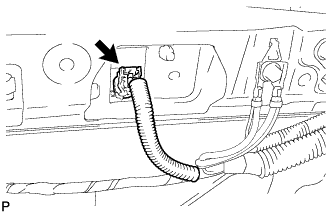
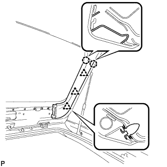
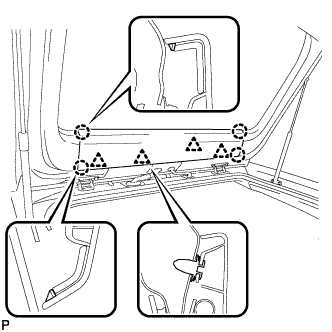
INSTALL NOISE FILTER
-
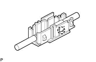
Engage the claw to install a new terminal cover to the wire harness.
-
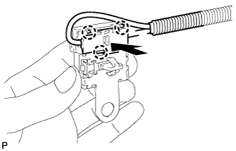
Engage the 3 claws to install the new terminal cover with the wire harness to a new condenser.
-
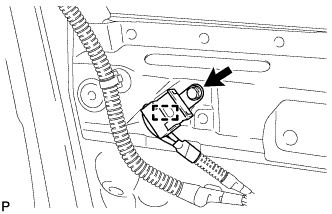
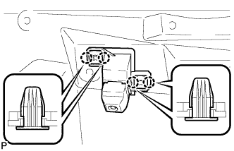
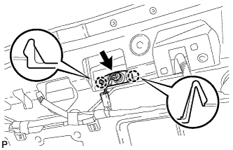
Engage the clamp to temporarily install a new noise filter with the wire harness to the back door.
-
Install the new noise filter with the bolt.
- Torque:
- 5.5 N*m { 56 kgf*cm, 49 in.*lbf }
-
-
INSTALL REAR TELEVISION CAMERA ASSEMBLY (w/ Rear Monitor)
-
Engage the 4 claws to temporarily install the rear television camera assembly.
-
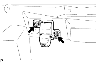
Install the rear television camera assembly with the 2 screws.
-
Connect the connector.
-
-
INSTALL REAR WIPER MOTOR ASSEMBLY
-
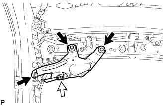
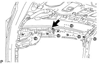
Install the rear wiper motor assembly with the 3 bolts.
- Torque:
- 5.5 N*m { 56 kgf*cm, 49 in.*lbf }
-
Connect the connector.
-
-
INSTALL REAR WIPER MOTOR GROMMET
-
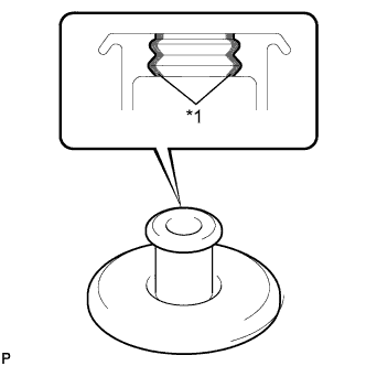
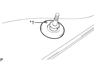
Text in Illustration *1 MP grease Apply MP grease to the entire surface of the rear wiper motor grommet lip.
Tech Tips
Make sure that the hole does not get clogged with grease and the grooves on the lip are filled with grease.
-
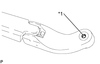
Install the rear wiper motor grommet.
Tech Tips
Install the grommet with its alignment mark facing up.
Text in Illustration *1 Alignment Mark
-
-
INSTALL REAR WIPER ARM AND BLADE ASSEMBLY
-
Operate the wiper and stop the windshield wiper motor at the automatic stop position.
-
When reusing the rear wiper arm and blade assembly:
-
Text in Illustration *1 Wiper Arm Serration Clean the wiper arm serrations.
-
-
When reusing the rear wiper motor assembly:
-
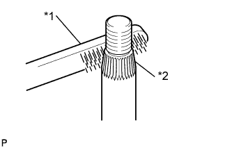
Text in Illustration *1 Wire Brush *2 Wiper Pivot Serration Clean the wiper pivot serrations with a wire brush.
-
-
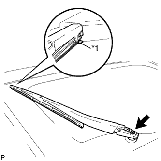
Text in Illustration *1 Ceramic Dot Install the rear wiper arm and blade assembly with the nut to the position shown in the illustration.
- Torque:
- 5.5 N*m { 56 kgf*cm, 49 in.*lbf }
Tech Tips
Hold the wiper arm by hand while tightening the nut.
-
Operate the rear wiper while spraying washer fluid onto the back door glass. Make sure that the rear wiper functions properly and the wiper does not come into contact with the vehicle body.
-
w/ Steel Wiper Arm:
-
Close the rear wiper arm head cap.
-
-
-
INSTALL REAR WIPER ARM HEAD CAP (w/ Resin Wiper Arm)
-
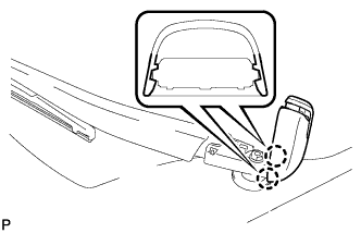
Engage the 2 claws to install the rear wiper arm head cap.
-
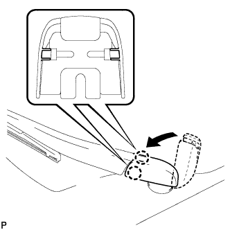
Engage the 2 claws to close the rear wiper arm head cap as shown in the illustration.
-
-
INSTALL REAR WASHER NOZZLE
-
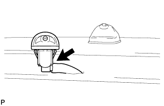
Connect the washer hose.
-
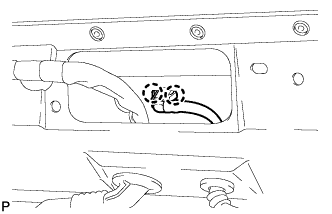
Engage the 2 claws to install the rear washer nozzle.
-
-
INSPECT REAR WASHER NOZZLE
-
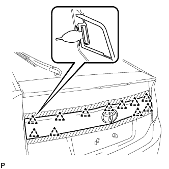
With the engine running, check that the center stream of washer fluid sprays on the windshield within the hatched area shown in the illustration.
Standard Washer fluid hits the windshield in the area shown in the illustration. 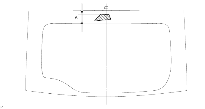
Standard Clearance Area Measurement A 48.7 mm (1.92 in.) Tech Tips
If the result is not as specified, replace the malfunctioning rear washer nozzle.
-
-
ADJUST REAR WASHER NOZZLE
-
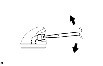
Using a screwdriver, adjust the direction of the rear washer nozzle.
Note
Do not use a safety pin or other pointed tools. Doing so may damage the inside of the washer nozzle.
Tech Tips
Use a thin-bladed screwdriver with an approximately 1 mm (0.0394 in.) thick tip.
-
-
INSTALL REAR SPOILER ASSEMBLY
-
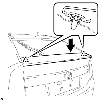
Engage the 2 clips to install the rear spoiler assembly.
-
Install the 5 nuts.
- Torque:
- 9.0 N*m { 92 kgf*cm, 80 in.*lbf }
-
Connect the connector.
-
-
INSTALL LICENSE PLATE LIGHT ASSEMBLY LH
-
Engage the 2 claws to install the license plate light assembly.
-
Connect the connector.
-
-
INSTALL LICENSE PLATE LIGHT ASSEMBLY RH
Tech Tips
Use the same procedure for the RH side and LH side.
-
INSTALL BACK DOOR OUTSIDE GARNISH SUB-ASSEMBLY
-
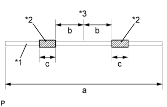
Text in Illustration *1 String *2 Double-sided Tape *3 Center line Wind double-sided tape around a string as shown in the illustration.
Tech Tips
The string is used to prevent the edge of the No. 2 back window lower moulding from being tucked under the back door outside garnish sub-assembly during installation.
Standard Dimension a 1600.0 mm (62.992 in.) b 50.0 to 75.0 mm (1.969 to 2.953 in.) c 30.0 mm (1.181 in.) -
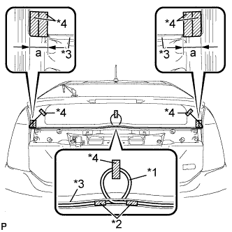
Text in Illustration *1 String *2 Double-sided Tape *3 No. 2 back window lower moulding *4 Tape Lift the ends of the No. 2 back window molding lower, and attach each end to the back door glass with tape.
Standard Dimension a 40.0 mm (1.575 in.) -
Make a loop in the center of the string, and attach it to the back of the No. 2 back window lower moulding with the double-sided tape on the string.
-
Attach the loop and ends of the string to the back door glass with tape as shown in the illustration.
-
Install the 4 new gaskets to the back door outside garnish sub-assembly.
-
Install 11 new clips (back door outside garnish clip) to the back door outside garnish sub-assembly.
-
Engage the 11 clips to install the back door outside garnish sub-assembly.
Tech Tips
Make sure that the string does not get pulled out from the back of the No. 2 back window molding lower.
-
Install the 4 nuts.
-
Apply soapy water to the No. 2 back window molding lower.
-
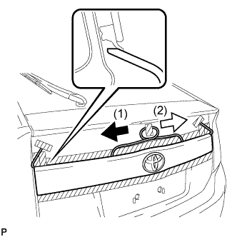
Remove the string by slowly pulling out toward each end from the center toward the sides of the vehicle as shown in the illustration.
Note
Do not damage the No. 2 back window lower moulding.
-
Check that the No. 2 back window molding lower is not pinched between the back door and the back door outside garnish sub-assembly.
-
Remove the tape.
-
-
INSTALL BACK DOOR STAY BOLT LH
-
Clean the threaded portion on the vehicle body with a non-residue solvent.
-
Apply adhesive to the threads of the back door stay bolt.
Adhesive Toyota Genuine Adhesive 1324, Three Bond 1324 or equivalent -
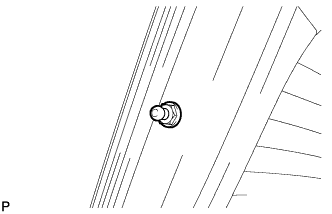
Install the back door stay bolt.
- Torque:
- 22 N*m { 224 kgf*cm, 16 ft.*lbf }
-
-
INSTALL BACK DOOR STAY BOLT RH
Tech Tips
Use the same procedure for the RH side and LH side.
-
INSTALL BACK DOOR STAY ASSEMBLY LH
Note
-
Avoid touching the piston rod as much as possible to prevent foreign matter from attaching to it. Be sure to hold the cylinder while servicing.
-
Do not wear cotton gloves or other similar materials when handling the piston rod. Fibers may attach to the rod and result in gas leaks.
-
Do not apply any horizontal load to the door stay in order to prevent the rod from deforming.
-
When reusing the back door stay assembly:
-
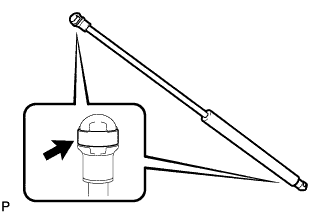
Install the 2 stop rings to the back door stay assembly.
-
-
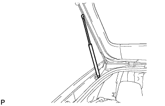
Install the back door stay assembly.
Note
Install the back door stay assembly while supporting the back door by hand.
-
Check that the back door stay assembly is engaged in the ball joint and that the back door stay assembly cannot be pulled out.
-
-
INSTALL BACK DOOR STAY ASSEMBLY RH
Tech Tips
Use the same procedure for the RH side and LH side.
-
INSTALL LOWER BACK DOOR STOPPER LH
-
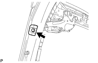
Install the lower back door stopper LH with the bolt.
-
-
INSTALL LOWER BACK DOOR STOPPER RH
Tech Tips
Use the same procedure for the RH side and LH side.
-
INSTALL BACK DOOR LOCK STRIKER ASSEMBLY
-
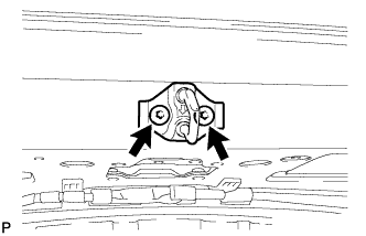
Using a T40 "TORX" socket wrench, install the back door lock striker assembly with the 2 screws.
- Torque:
- 23 N*m { 235 kgf*cm, 17 ft.*lbf }
-
-
INSTALL LOWER BACK DOOR STOPPER CUSHION
-
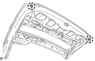
Engage the claws to install the 2 new lower back door stopper cushions.
-
-
INSTALL BACK DOOR LOCK STRIKER COVER
-
Engage the 2 claws to install the back door lock striker cover.
-
-
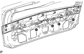
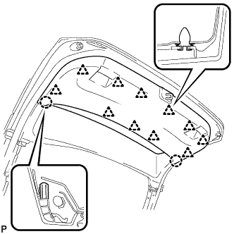
INSTALL BACK DOOR TRIM BOARD
-
Engage the 5 clips and 2 guides to install the back door trim board.
-
-
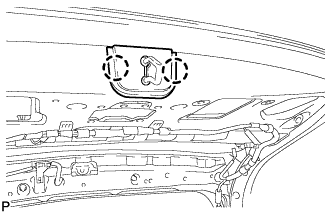
INSTALL BACK DOOR TRIM BOARD ASSEMBLY
-
Engage the 11 clips and 2 claws to install the back door panel trim assembly.
-
-
INSTALL BACK DOOR SIDE GARNISH LH
-
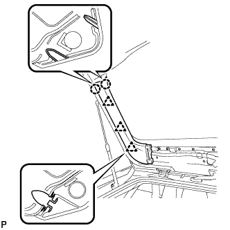
Engage the 3 clips and 2 claws to install the back door side garnish LH.
-
-
INSTALL BACK DOOR SIDE GARNISH RH
-
Engage the 3 clips and 2 claws to install the back door side garnish RH.
-
-
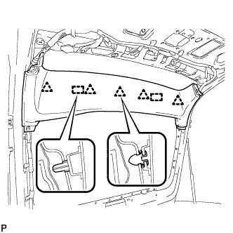
INSTALL UPPER BACK DOOR TRIM PANEL ASSEMBLY
-
Engage the 4 clips and 4 claws to install the upper back door trim panel assembly.
-