BACK DOOR DISASSEMBLY

-
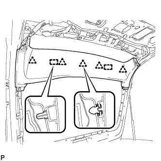
REMOVE UPPER BACK DOOR TRIM PANEL ASSEMBLY
-
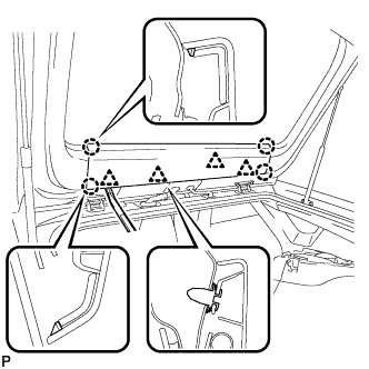
Using a moulding remover, disengage the 4 clips and 4 claws, and remove the upper back door trim panel assembly.
-
-
REMOVE BACK DOOR SIDE GARNISH RH
-
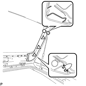
Disengage the 3 clips and 2 claws, and remove the back door side garnish RH.
-
-
REMOVE BACK DOOR SIDE GARNISH LH
-
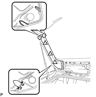
Disengage the 3 clips and 2 claws, and remove the back door side garnish LH.
-
-
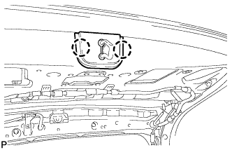
REMOVE BACK DOOR TRIM BOARD ASSEMBLY
-
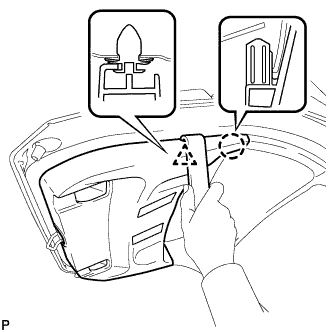
Using a moulding remover, disengage the clip and claw.
-
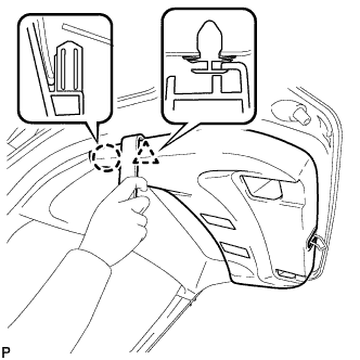
Using a moulding remover, disengage the clip and claw.
-
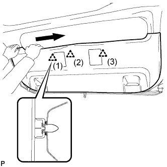
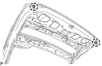
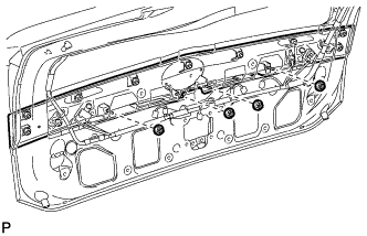
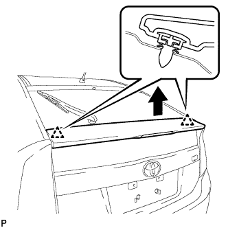
Disengage the 3 clips in the order shown in the illustration.
-
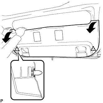
Disengage the 2 clips by pulling the back door trim board assembly in the direction indicated by the arrows in the illustration.
-
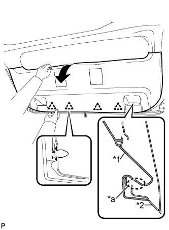
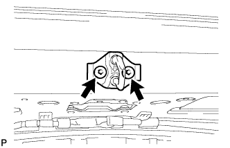
Text in Illustration *1 Back Door Trim Board Assembly *2 Back Door Panel *a The portion that may be damaged due to interference Remove the back door trim board assembly by pulling it in the direction indicated by the arrow in the illustration to disengage the 4 clips.
Note
Make sure to pull the back door trim board assembly in the direction indicated by the arrow in the illustration. If the back door trim board assembly is removed from the lower part, the door pull handle mounting area may interfere with the back door panel, resulting in damage to the back door trim board assembly.
-
-
REMOVE BACK DOOR TRIM BOARD
-
Disengage the 5 clips and 2 guides, and remove the back door trim board.
-
-
REMOVE BACK DOOR LOCK STRIKER COVER
-
Disengage the 2 claws and remove the back door lock striker cover.
-
-
REMOVE LOWER BACK DOOR STOPPER CUSHION
-
Disengage the claws to remove the 2 lower back door stopper cushions.
-
-
REMOVE BACK DOOR LOCK STRIKER ASSEMBLY
-
Using a T40 "TORX" socket wrench, remove the 2 screws and back door lock striker assembly.
-
-
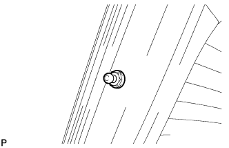
REMOVE LOWER BACK DOOR STOPPER LH
-
Remove the bolt and lower back door stopper LH.
-
-
REMOVE LOWER BACK DOOR STOPPER RH
Tech Tips
Use the same procedure for the RH side and LH side.
-
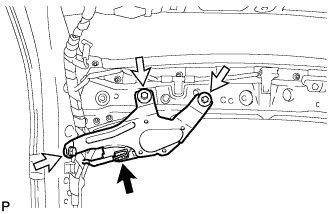
REMOVE BACK DOOR STAY ASSEMBLY LH
Note
-
Avoid touching the piston rod as much as possible to prevent foreign matter from attaching to it. Be sure to hold the cylinder while servicing.
-
Do not wear cotton gloves or other similar materials when handling the piston rod. Fibers may attach to the rod and result in gas leaks.
-
Do not apply any horizontal load to the door stay in order to prevent the piston rod from deforming.
-
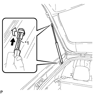
Text in Illustration *1 Protective Tape Using a screwdriver, remove the stop ring along the groove.
Tech Tips
Tape the screwdriver tip before use.
-
Release the ball joint and remove the back door stay assembly.
Note
Remove the back door stay assembly while supporting the back door by hand.
-
-
REMOVE BACK DOOR STAY ASSEMBLY RH
Tech Tips
Use the same procedure for the RH side and LH side.
-
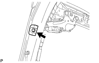
REMOVE BACK DOOR STAY BOLT LH
-
Remove the back door stay bolt.
-
-
REMOVE BACK DOOR STAY BOLT RH
Tech Tips
Use the same procedure for the RH side and LH side.
-
REMOVE BACK DOOR OUTSIDE GARNISH SUB-ASSEMBLY
-
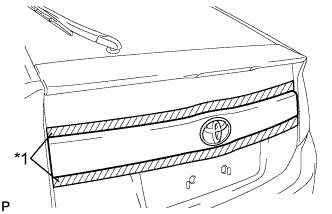
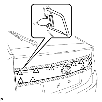
Text in Illustration *1 Protective Tape Put protective tape around the back door outside garnish sub-assembly.
-
Remove the 4 nuts.
-
Disengage the 11 clips and remove the back door outside garnish sub-assembly.
-
Remove the 11 clips (back door outside garnish clip) from the back door outside garnish sub-assembly.
-
Remove the 4 gaskets from the back door outside garnish sub-assembly.
-
-
REMOVE LICENSE PLATE LIGHT ASSEMBLY LH
-
Disconnect the connector.
-
Disengage the 2 claws and remove the license plate light assembly.
-
-
REMOVE LICENSE PLATE LIGHT ASSEMBLY RH
Tech Tips
Use the same procedure for the RH side and LH side.
-
REMOVE REAR SPOILER ASSEMBLY
-
Disconnect the connector.
-
Remove the 5 nuts.
-
Disengage the 2 clips to remove the rear spoiler assembly.
-
-
REMOVE REAR WASHER NOZZLE
-
Disengage the 2 claws.
-
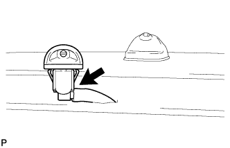
Disconnect the washer hose and remove the rear washer nozzle.
-
-
REMOVE REAR WIPER ARM HEAD CAP (w/ Resin Wiper Arm)
-
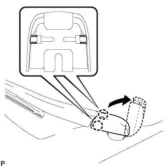
Disengage the 2 claws and open the rear wiper arm head cap as shown in the illustration.
-
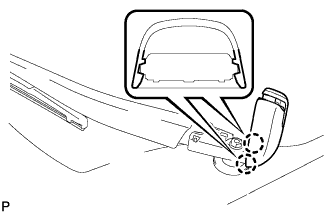
Disengage the 2 claws and remove the rear wiper arm head cap.
-
-
REMOVE REAR WIPER ARM AND BLADE ASSEMBLY
-
w/ Resin Wiper Arm:
-
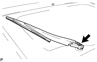
Remove the nut, and the rear wiper arm and blade assembly.
-
-
w/ Steel Wiper Arm:
-
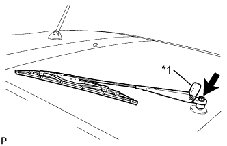
Text in Illustration *1 Rear Wiper Arm Head Cap Open the rear wiper arm head cap.
-
Remove the nut and the rear wiper arm and blade assembly.
-
-
-
REMOVE REAR WIPER MOTOR GROMMET
-
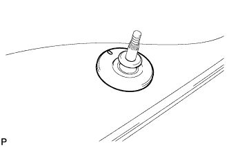
Remove the rear wiper motor grommet.
-
-
REMOVE REAR WIPER MOTOR ASSEMBLY
-
Disconnect the connector.
-
Remove the 3 bolts and the rear wiper motor assembly.
-
-
REMOVE REAR TELEVISION CAMERA ASSEMBLY (w/ Rear Monitor)
-
Disconnect the connector.
-
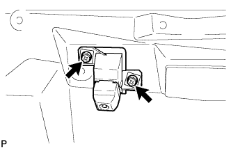
Remove the 2 screws.
-
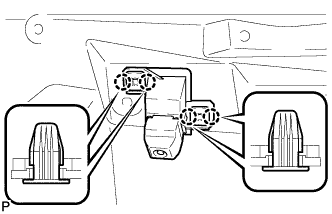
Disengage the 4 claws and remove the rear television camera assembly.
-
-
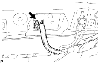
REMOVE NOISE FILTER
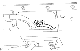
Note
When the terminal cover is removed, the noise filter must be replaced because the terminal cover and condenser are supplied as a set.
-
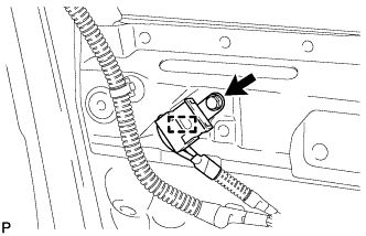
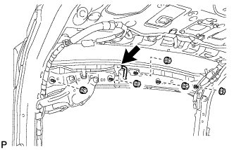
Remove the bolt.
-
Disengage the clamp and disconnect the noise filter with the wire harness from the vehicle body.
-
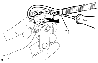
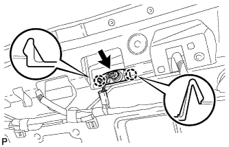
Text in Illustration *1 Protective Tape Using a screwdriver wrapped with protective tape, disengage the 3 claws and remove the terminal cover with the wire harness from the condenser.
-
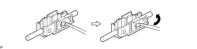
Using a screwdriver, bend back and break off the claw as shown in the illustration.
-
Remove the terminal cover from the wire harness.
-