WINDOW DEFOGGER SYSTEM Rear Window Defogger System does not Operate
DESCRIPTION
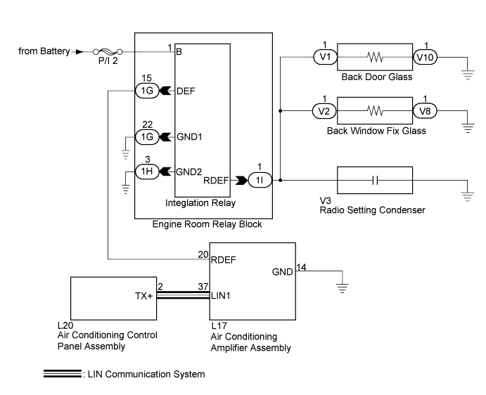
When the rear window defogger switch on the air conditioning control panel assembly is pressed, the operation signal is transmitted to the air conditioning amplifier assembly through a LIN communication line. When the air conditioning amplifier assembly receives the signal, it turns on the integration relay to operate the rear window defogger.
WIRING DIAGRAM
INSPECTION PROCEDURE
Note
-
Inspect the fuses for circuits related to this system before performing the following inspection procedure.
PROCEDURE
-
CHECK REAR WINDOW DEFOGGER SYSTEM
-
Activate the rear defogger system and check the symptoms.
Result Result Proceed to Both back window defoggers do not warm up. A The back door glass defogger does not warm up. B The back window fix glass defogger does not warm up. C
B 
CHECK HARNESS AND CONNECTOR (INTEGRATION RELAY - BACK DOOR GLASS) Click here
C
CHECK HARNESS AND CONNECTOR (INTEGRATION RELAY - BACK WINDOW FIX GLASS) Click here
A 
-
-
CHECK POWER STEERING SYSTEM (Battery Voltage Lo Record)
-
Connect the intelligent tester to the DLC3.
-
Turn the power switch on (IG).
-
Turn the intelligent tester on.
-
Enter the following menus: Chassis / EMPS / Data List.
-
Read the Data List according to the display on the intelligent tester.
EMPS Tester Display Measurement item/Range Normal Condition Diagnostic Note Battery Voltage Lo Record Battery voltage reduction history/ Min.: 0 times, Max.: 65535 times 0 to 65535 - Result Result Proceed to No control history is stored. A Control history is stored. B
B 
GO TO CHARGING SYSTEM Click here
A
-
-
PERFORM ACTIVE TEST USING INTELLIGENT TESTER (DEFOGGER RELAY)
-
Enter the following menus: Body / Air Conditioner / Active Test.
-
Perform the Active Test according to the display on the intelligent tester.
Air Conditioner Tester Display Test Part Control Range Diagnostic Note Defogger Relay (Rear) Rear window defogger ON/OFF - OK The window defogger system operates normally.
NG
CHECK HARNESS AND CONNECTOR (AIR CONDITIONING AMPLIFIER ASSEMBLY - INTEGRATION RELAY) Click here
OK 
GO TO AIR CONDITIONING SYSTEM Click here
-
-
CHECK HARNESS AND CONNECTOR (AIR CONDITIONING AMPLIFIER ASSEMBLY - INTEGRATION RELAY)
-
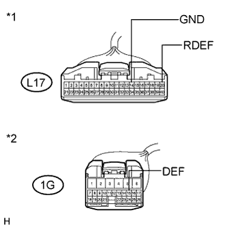
Text in Illustration *1 Front view of wire harness connector
(to Air Conditioning Amplifier Assembly)
*2 Front view of wire harness connector
(to Integration Relay)
Disconnect the 1G integration relay connector.
-
Disconnect the L17 air conditioning amplifier assembly connector.
-
Measure the resistance according to the value(s) in the table below.
Standard Resistance Tester Connection Condition Specified Condition L17-20 (RDEF) - 1G-15 (DEF) Always Below 1 Ω 1G-15 (DEF) - Body ground Always 10 kΩ or higher L17-14 (GND) - Body ground Always Below 1 Ω
NG
REPAIR OR REPLACE HARNESS OR CONNECTOR
OK
-
-
CHECK AIR CONDITIONING AMPLIFIER ASSEMBLY
-
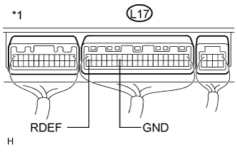
Text in Illustration *1 Rear view of wire harness connector
(to Air Conditioning Amplifier Assembly)
Turn the power switch on (READY).
-
Measure the voltage according to the value(s) in the table below.
Standard Voltage Tester Connection Condition Specified Condition L17-20 (RDEF) - L17-14 (GND) Rear defogger switch off 11 to 14 V L17-20 (RDEF) - L17-14 (GND) Rear defogger switch on Below 1 V
NG
REPLACE AIR CONDITIONING AMPLIFIER ASSEMBLY Click here
OK
-
-
INSPECT RADIO SETTING CONDENSER
-
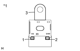
Text in Illustration *1 Radio Setting Condenser Remove the radio setting condenser.
-
Measure the resistance according to the value(s) in the table below.
Standard Resistance Tester Connection Condition Specified Condition 1 - 2 Always 10 kΩ or higher 2 - 3 Always Below 1 Ω
NG
REPLACE RADIO SETTING CONDENSER
OK
-
-
CHECK HARNESS AND CONNECTOR (INTEGRATION RELAY - BODY GROUND)
-
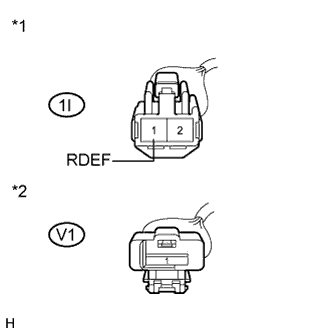
Text in Illustration *1 Front view of wire harness connector
(to Integration Relay)
*2 Front view of wire harness connector
(to Back Door Glass)
Disconnect the V1 back door glass battery side connector.
-
Disconnect the V2 back window fix glass battery side connector.
-
Disconnect the 1I integration relay connector.
-
Measure the resistance according to the value(s) in the table below.
Standard Resistance Tester Connection Condition Specified Condition 1I-1 (RDEF) - Body ground Always 10 kΩ or higher 1I-1 (RDEF) - V1-1 Always Below 1 Ω
NG
REPAIR OR REPLACE HARNESS OR CONNECTOR
OK
REPLACE INTEGRATION NO.1 RELAY Click here
-
-
CHECK HARNESS AND CONNECTOR (INTEGRATION RELAY - BACK DOOR GLASS)
-
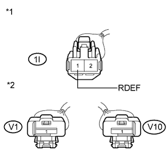
Text in Illustration *1 Front view of wire harness connector
(to Integration Relay)
*2 Front view of wire harness connector
(to Back Door Glass)
Disconnect the V1 back door glass battery side connector.
-
Disconnect the V10 back door glass body ground side connector.
-
Measure the resistance according to the value(s) in the table below.
Standard Resistance Tester Connection Condition Specified Condition 1I-1 (RDEF) - V1-1 Always Below 1 Ω V10-1 - Body ground Always Below 1 Ω 1I-1 (RDEF) - Body ground Always 10 kΩ or higher V1-1 - Body ground Always 10 kΩ or higher
NG
REPAIR OR REPLACE HARNESS OR CONNECTOR
OK
REPLACE BACK DOOR GLASS Click here
-
-
CHECK HARNESS AND CONNECTOR (INTEGRATION RELAY - BACK WINDOW FIX GLASS)
-
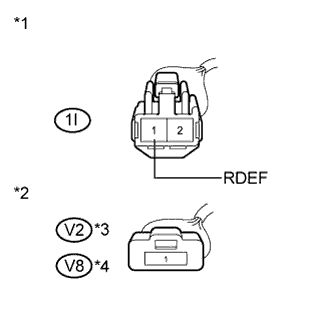
Text in Illustration *1 Front view of wire harness connector
(to Integration Relay)
*2 Front view of wire harness connector
(to Back Window Fix Glass)
*3 Back Window Fix Glass Battery Side *4 Back Window Fix Glass Body Ground Side Disconnect the V2 back window fix glass battery side connector.
-
Disconnect the V8 back window fix glass body ground side connector.
-
Measure the resistance according to the value(s) in the table below.
Standard Resistance Tester Connection Condition Specified Condition 1I-1 (RDEF) - V2-1 Always Below 1 Ω V8-1 - Body ground Always Below 1 Ω 1I-1 (RDEF) - Body ground Always 10 kΩ or higher V2-1 - Body ground Always 10 kΩ or higher
NG
REPAIR OR REPLACE HARNESS OR CONNECTOR
OK
REPLACE BACK WINDOW FIX GLASS Click here
-