POWER WINDOW REGULATOR MOTOR (for Front Door) INSTALLATION

Tech Tips
-
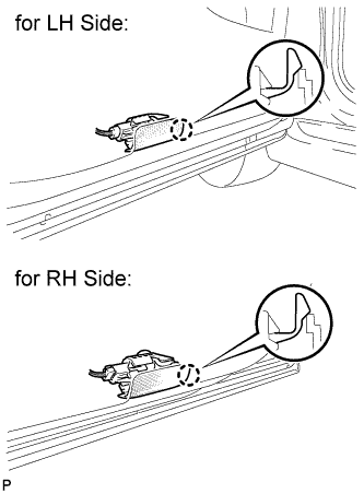
Use the same procedure for the RH side and LH side.
-
The procedure listed below is for the LH side.
-
INSTALL FRONT POWER WINDOW REGULATOR MOTOR ASSEMBLY
Note
The regulator arm must be below the intermediate position when installing the front power window regulator motor assembly.
-
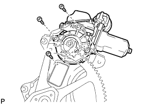
Using a T25 "TORX" driver, install the front power window regulator motor assembly with the 3 screws.
- Torque:
- 5.4 N*m { 55 kgf*cm, 48 in.*lbf }
Tech Tips
A new front window regulator uses self-tapping screws to thread new installation holes when the self-tapping screws are inserted.
-
-
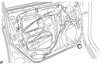
INSTALL FRONT DOOR WINDOW REGULATOR ASSEMBLY
-
Apply MP grease to the sliding parts of the front door window regulator assembly.
-
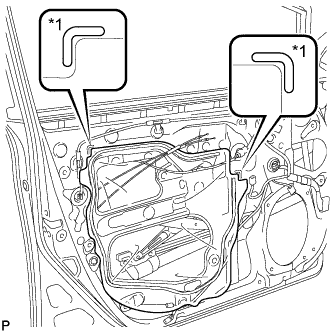
Install the temporary bolt to the front door window regulator assembly.
-
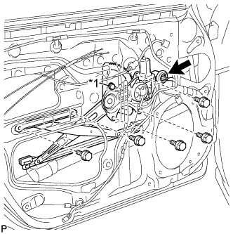
Text in Illustration *1 Temporary Bolt Temporarily install the front door window regulator assembly.
-
Tighten the temporary bolt and 5 bolts.
- Torque:
- 8.0 N*m { 82 kgf*cm, 71 in.*lbf }
-
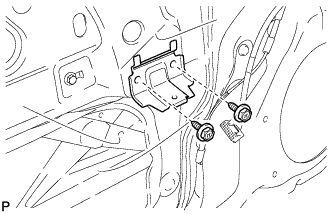
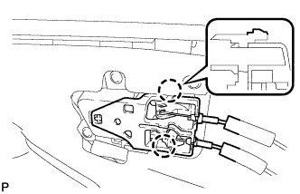
Connect the connector.
-
-
INSTALL FRONT DOOR GLASS SUB-ASSEMBLY
-
Connect the cable to the negative (-) battery terminal.
-
Connect the power window regulator master switch assembly and move the front door glass sub-assembly so that the door glass bolts can be seen.
-
w/ Navigation System for HDD:
Note
After the power switch is turned off, the display and navigation module display (HDD navigation system) records various types of memory and settings. As a result, after turning the power switch off, make sure to wait at least 60 seconds before disconnecting the cable from the negative (-) battery terminal.
-
-
Disconnect the cable from the negative (-) battery terminal and power window regulator master switch assembly.
-
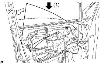
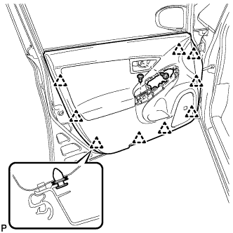
Insert the front door glass sub-assembly into the front door panel along the front door glass run as indicated by the arrows, in the order shown in the illustration.
-
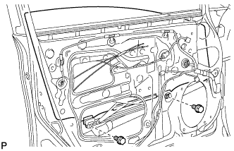
Install the front door glass sub-assembly with the 2 bolts.
- Torque:
- 8.0 N*m { 82 kgf*cm, 71 in.*lbf }
-
Install the grommet.
-
Connect the cable to the negative (-) battery terminal.
Note
When disconnecting the cable, some systems need to be initialized after the cable is reconnected Click here.
-
-
INSTALL FRONT DOOR SERVICE HOLE COVER
-
Apply butyl tape to the front door panel.
-
Text in Illustration *1 Reference Point Pass the front door lock remote control cable assembly and front door inside locking cable assembly through a new front door service hole cover.
-
Attach the front door service hole cover according to the reference points on the front door panel.
Note
Securely install the front door service hole cover preventing wrinkles and air bubbles.
-
-
INSTALL FRONT DOOR TRIM BRACKET
-
Install the front door trim bracket with the 2 screws.
-
-
INSTALL FRONT DOOR INSIDE HANDLE SUB-ASSEMBLY
-
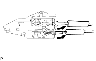
Connect the front door lock remote control cable assembly and front door inside locking cable assembly to the front door inside handle.
-
Engage the 2 claws and install the front door inside handle sub-assembly to the front door trim board sub-assembly.
-
-
INSTALL FRONT DOOR TRIM BOARD SUB-ASSEMBLY
-
Engage the 9 clips and install the front door trim board sub-assembly.
-
Install the 2 screws.
-
Remove the 2 pieces of protective tape.
-
-
INSTALL COURTESY LIGHT ASSEMBLY
-
Connect the connector.
-
Engage the claw to install the courtesy light assembly.
-
-
INSTALL DOOR ARMREST COVER
-
Install the door armrest cover.
-
-
INSTALL POWER WINDOW REGULATOR MASTER SWITCH ASSEMBLY WITH FRONT DOOR ARMREST BASE PANEL (for Driver Side)
-
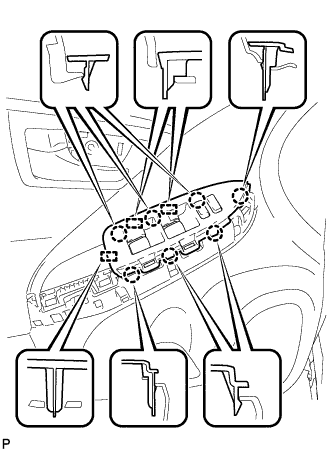
Connect the connector.
-
Engage the 7 claws and 3 guides, and install the power window regulator master switch assembly with front door armrest base panel.
-
-
INSTALL POWER WINDOW REGULATOR SWITCH ASSEMBLY WITH FRONT DOOR ARMREST BASE PANEL (for Front Passenger Side)
-
Connect the connector.
-
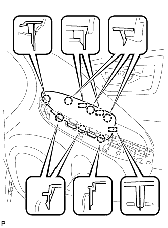
Engage the 7 claws and 3 guides, and install the power window regulator switch assembly with front door armrest base panel.
-
-
INSTALL ASSIST GRIP COVER
-
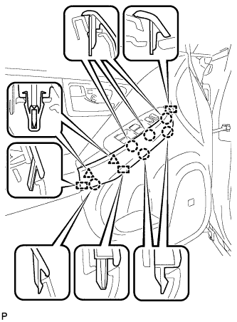
Engage the 6 claws, 2 clips and 3 guides, and install the assist grip cover.
-
-
INSTALL FRONT DOOR INSIDE HANDLE BEZEL PLUG
-
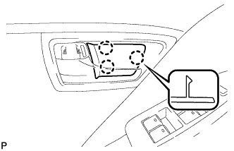
Engage the 3 claws and install the front door inside handle bezel plug.
-
-
INSTALL REAR NO. 3 FLOOR BOARD
-

Engage the 2 guides to install the rear No. 3 floor board.
-
-
INSTALL REAR DECK FLOOR BOX
-
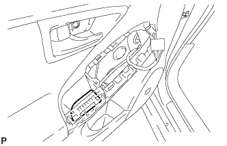
Install the rear deck floor box.
-
-
INSTALL REAR NO. 2 FLOOR BOARD
-

Engage the 3 guides <A>.
-
Engage the 2 guides <B> and install the rear No. 2 floor board as shown in the illustration.
-
-
INITIALIZE POWER WINDOW CONTROL SYSTEM