WINDSHIELD GLASS REMOVAL

-
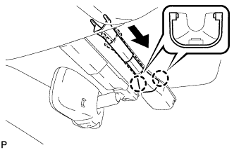
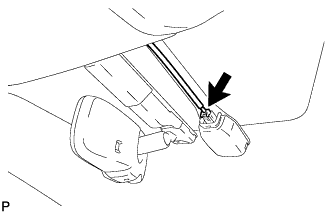
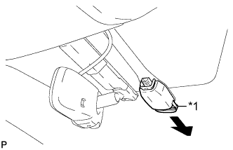
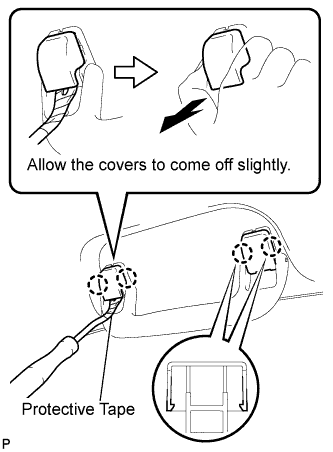
REMOVE FRONT WIPER ARM HEAD CAP
-
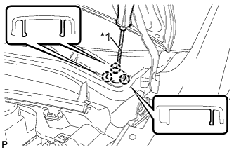
Text in Illustration *1 Protective Tape Using a screwdriver, disengage the 3 claws to remove the front wiper arm head cap.
Tech Tips
-
Tape the screwdriver tip before use.
-
Use the same procedure for the RH side and LH side.
-
-
-
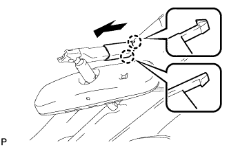
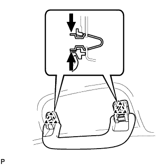
REMOVE FRONT WIPER ARM AND BLADE ASSEMBLY LH
-
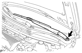
Remove the nut and the front wiper arm and blade assembly LH.
-
-
REMOVE FRONT WIPER ARM AND BLADE ASSEMBLY RH
-
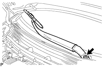
Remove the nut and the front wiper arm and blade assembly RH.
-
-
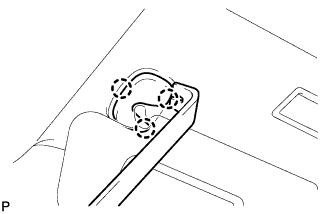
REMOVE COWL SIDE VENTILATOR SUB-ASSEMBLY LH
-
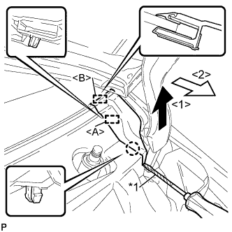
Text in Illustration *1 Protective Tape Using a screwdriver, disengage the claw and guide <A> as shown in the illustration.
Tech Tips
Tape the screwdriver tip before use.
-
Disengage the guide <B> and remove the cowl side ventilator sub-assembly LH as shown in the illustration.
-
-
REMOVE COWL SIDE VENTILATOR SUB-ASSEMBLY RH
Tech Tips
Use the same procedure as for the LH side.
-
REMOVE COWL TOP VENTILATOR LOUVER SUB-ASSEMBLY (for LHD)
-
Remove the 2 clips.
-
Disengage the 5 claws and 3 guides <A>.
-
Disengage the 8 guides <B> and pull out the cowl top ventilator louver sub-assembly as shown in the illustration.
-
-
REMOVE COWL TOP VENTILATOR LOUVER SUB-ASSEMBLY (for RHD)
-
Remove the 2 clips.
-
Disengage the 6 claws and 3 guides <A>.
-
Disengage the 8 guides <B> and pull out the cowl top ventilator louver sub-assembly as shown in the illustration.
-
-
REMOVE RAIN SENSOR COVER (w/ Rain Sensor)
-
Disconnect the rain sensor cover as shown in the illustration.
-
Disengage the 2 claws and remove the rain sensor cover.
-
-
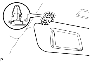
REMOVE RAIN SENSOR (w/ Rain Sensor)
-
Disconnect the connector.
-
Text in Illustration *1 Stopper Release the stopper by pulling the stopper down and disconnect the rain sensor as shown in the illustration.
-
-
REMOVE INNER REAR VIEW MIRROR COVER (w/ EC Mirror)
-
Disengage the 2 claws and slide the inner rear view mirror cover as shown in the illustration.
-
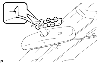
Disengage the 6 claws and remove the inner rear view mirror cover.
-
-
REMOVE INNER REAR VIEW MIRROR ASSEMBLY (w/o EC Mirror)
-
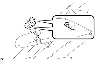
Disengage the 2 claws and disconnect the inner rear view mirror cover.
-
Remove the inner rear view mirror as shown in the illustration.
-
-
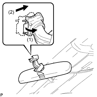
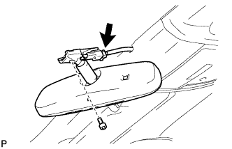
REMOVE INNER REAR VIEW MIRROR ASSEMBLY (w/ EC Mirror)
-
Disconnect the connector.
-
Using "TORX" socket wrench (T20), remove the screw and inner rear view mirror assembly.
-
-
DISCONNECT FRONT DOOR OPENING TRIM WEATHERSTRIP LH
-
REMOVE FRONT PILLAR GARNISH LH
-
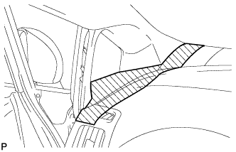
When removing the front pillar garnish LH, cover the shaded part in the illustration with a piece of cloth so that the interior parts will not be damaged.
-
Text in Illustration *1 Front Pillar Garnish Clip Pull the upper part of the garnish toward the inside of the cabin and disengage the 2 clips.
Tech Tips
Make the front pillar garnish LH hang down from the front pillar garnish clip.
-
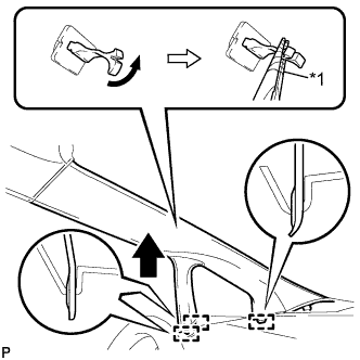
Turn the end of the front pillar garnish clip 90° with needle-nosed pliers and remove it from the front pillar garnish LH.
Note
-
Front pillar garnish clips are reusable if they are not removed from the vehicle and have no damage.
-
Replace the front pillar garnish clips with new ones if they are removed from the vehicle.
Tech Tips
Tape the needle-nosed pliers tip before use.
Text in Illustration *1 Protective Tape -
-
Disengage the 3 guides.
-
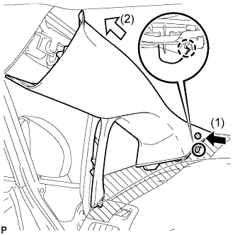
Disengage the claw while pressing the shaded part in the illustration in the direction indicated by the arrow (1).
-
Remove the front pillar garnish LH by pulling it in the direction indicated by the arrow (2) in the illustration.
-
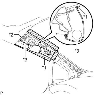
Text in Illustration *1 Adhesive Tape *2 Protective Cover *3 Curtain Shield Airbag Assembly Protect the curtain shield airbag assembly.
-
Cover the airbag with a cloth or piece of nylon and secure the ends of the cover with tape as shown in the illustration.
Note
Cover the curtain shield airbag with a protective cover as soon as the front pillar garnish is removed.
-
-
-
DISCONNECT FRONT DOOR OPENING TRIM WEATHERSTRIP RH
Tech Tips
Use the same procedure for the RH side and LH side.
-
REMOVE FRONT PILLAR GARNISH RH
Tech Tips
Use the same procedure for the RH side and LH side.
-
REMOVE ROOF TOP MOULDING
-
Using moulding remover B, disengage the 3 claws and 2 clips, and remove the roof top moulding.
-
-
REMOVE MAP LIGHT ASSEMBLY (w/o Sliding Roof)
-
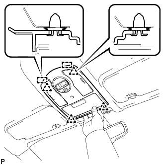
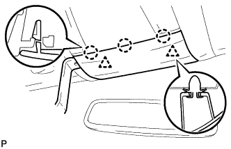
Disengage the 4 clips and 2 guides as shown in the illustration.
-
Disconnect the connector and remove the map light assembly.
-
-
REMOVE MAP LIGHT ASSEMBLY (w/ Sliding Roof)
-
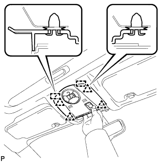
Disengage the 4 clips and 2 guides as shown in the illustration.
-
Disconnect the connector and remove the map light assembly.
-
-
REMOVE FRONT ASSIST GRIP ASSEMBLY
-
Using a clip remover, disengage the 4 claws.
Note
Do not forcibly pry the assist grip covers to prevent them from being deformed.
Tech Tips
-
Gently pry on the assist grip covers as shown in the illustration to remove them.
-
Tape the clip remover tip before use.
-
-
Pull off the 2 assist grip covers by hand.
-
Disengage the 2 clips and remove the front assist grip assembly.
-
Remove the 2 clips from the vehicle body.
Tech Tips
Use the same procedure for the other front assist grip.
-
-
REMOVE VISOR BRACKET COVER LH
-
Using moulding remover B, disengage the 3 claws and remove the visor bracket cover LH.
-
-
REMOVE VISOR ASSEMBLY LH
-
Disengage the 2 clips and remove the visor assembly LH.
-
-
REMOVE VISOR BRACKET COVER RH
Tech Tips
Use the same procedure for the RH side and LH side.
-
REMOVE VISOR ASSEMBLY RH
Tech Tips
Use the same procedure for the RH side and LH side.
-
REMOVE VISOR HOLDER
-
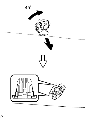
Turn the visor holder approximately 45° and pull it out as shown in the illustration.
-
Disengage the 2 claws and remove the visor holder.
Tech Tips
Use the same procedure for the other visor holder.
-
-
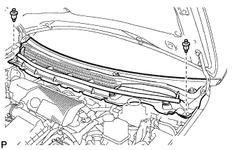
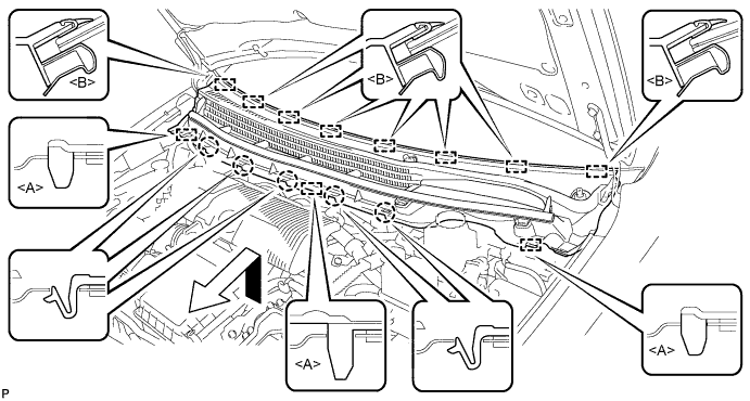
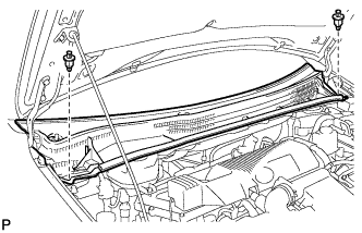
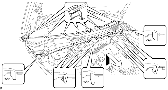
REMOVE ROOF HEADLINING ASSEMBLY
-
Slightly lower the front section of the roof headlining assembly so that the windshield glass can be removed.
Tech Tips
It is not necessary to completely remove the roof headlining assembly.
-
-
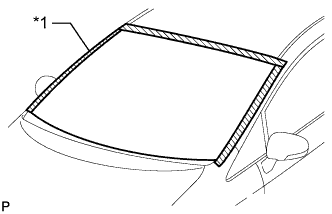
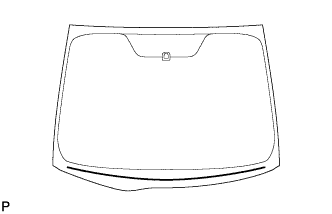
REMOVE WINDSHIELD GLASS SUB-ASSEMBLY
-
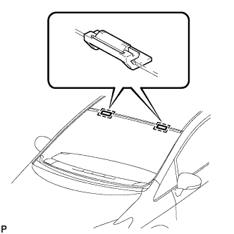
Text in Illustration *1 Protective Tape Apply protective tape to the installation position of the windshield glass sub-assembly on the vehicle body.
Tech Tips
Apply protective tape to the installation surface to prevent it from being scratched.
-
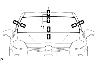
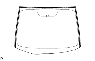
Text in Illustration *1 Matchmark Place matchmarks on the windshield glass sub-assembly and vehicle body on the locations indicated in the illustration.
Tech Tips
Matchmarks are not necessary if the windshield glass assembly is not going to be reused.
-
Text in Illustration *1 Piano Wire Pass a piano wire between the vehicle body and glass from the interior as shown in the illustration.
-
Tie both wire ends to wooden blocks or similar objects that can serve as handles.
-
Cut off the adhesive applied to the bottom of the windshield glass sub-assembly by pulling the piano wire under the glass.
Note
-
When separating the windshield glass sub-assembly, be careful not to damage the paint or interior and exterior ornaments.
-
To prevent the safety pad from being scratched when removing the windshield glass sub-assembly, place a plastic sheet between the piano wire and safety pad.
-
-
While pushing back the lip of the molding with a screwdriver, pass a piano wire between the vehicle body and windshield glass sub-assembly so that both wire ends are in the interior as shown in the illustration.
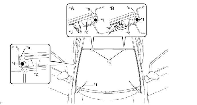
Text in Illustration *A 1-piece type *B 2-piece type *1 Piano Wire *2 Adhesive *3 No. 1 Stopper *4 No. 2 Stopper *a Lip of the molding *b Stopper -
Tie both wire ends to wooden blocks or similar objects that can serve as handles.
-
Cut off the adhesive by pulling the piano wire around the windshield glass sub-assembly.
Note
-
When separating the windshield glass sub-assembly, be careful not to damage the paint or interior and exterior ornaments.
-
To prevent the safety pad from being scratched when removing the windshield glass sub-assembly, place a plastic sheet between the piano wire and safety pad.
-
When passing the piano wire below the 2 stoppers, make sure to cut the adhesive applied between the windshield glass sub-assembly and stoppers.
-
Be careful not to drop the windshield glass sub-assembly.
-
-
Using suction cups, remove the windshield glass sub-assembly .
Note
-
Be careful not to drop the windshield glass sub-assembly.
-
Leave as much adhesive on the vehicle body as possible when removing the windshield glass sub-assembly.
-
-
Remove the parts of the 2 No. 1 windshield glass stoppers (1-piece type) or 2 No. 2 windshield glass stoppers (2-piece type) that remain on the vehicle.
-
-
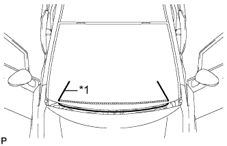
REMOVE WINDOW GLASS ADHESIVE DAM
-
Using a scraper, remove the windshield glass adhesive dam.
Note
-
Be careful not to damage the windshield glass.
-
Be sure to replace the window glass adhesive dam with a new one.
-
-
-
REMOVE WINDSHIELD OUTSIDE MOULDING
-
Using a scraper, remove the windshield outside moulding.
Note
-
Be careful not to damage the windshield glass.
-
Be sure to replace the windshield outside moulding with a new one.
-
-
-
REMOVE NO. 1 WINDSHIELD GLASS STOPPER (for 2-piece Type)
-
Remove the 2 No. 1 windshield glass stoppers.
Note
Be sure to replace the No. 1 windshield glass stoppers with new ones.
-
-
CLEAN WINDSHIELD GLASS
-
Using a scraper, remove the adhesive tape and adhesive sticking to the windshield glass.
Note
Be careful not to damage the windshield glass.
-
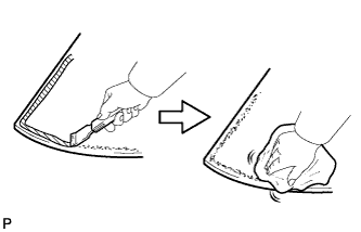
Clean the outer circumference of the windshield glass with a non-residue solvent.
Note
-
Do not touch the windshield glass surface after cleaning it.
-
Even if using a new windshield glass, clean the windshield glass with a non-residue solvent.
-
-
-
CLEAN VEHICLE BODY
-
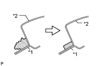
Text in Illustration *1 Adhesive *2 Body Clean and shape the contact surfaces of the vehicle body.
-
Using a knife, cut away excess adhesive on the contact surfaces of the vehicle body, as shown in the illustration.
Note
Be careful not to damage the vehicle body.
Tech Tips
Leave as much adhesive on the vehicle body as possible.
-
Clean the contact surfaces of the vehicle body with a piece of cloth saturated with cleaner.
Tech Tips
Even if all the adhesive has been removed, clean the vehicle body.
-
-