UPPER INSTRUMENT PANEL INSTALLATION

-
INSTALL UPPER INSTRUMENT PANEL ASSEMBLY
-
When using a new upper instrument panel sub-assembly:
-
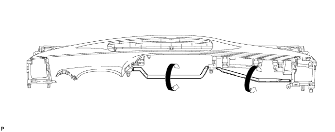
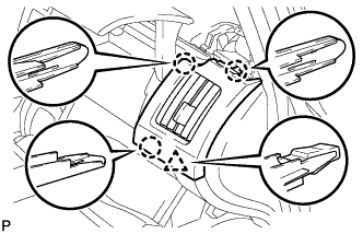
Immediately before installing the upper instrument panel assembly, twist and cut off the portions shown in the illustration.
-
-
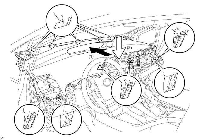
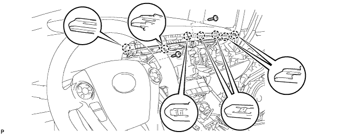
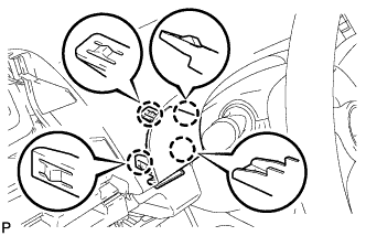
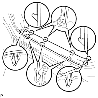
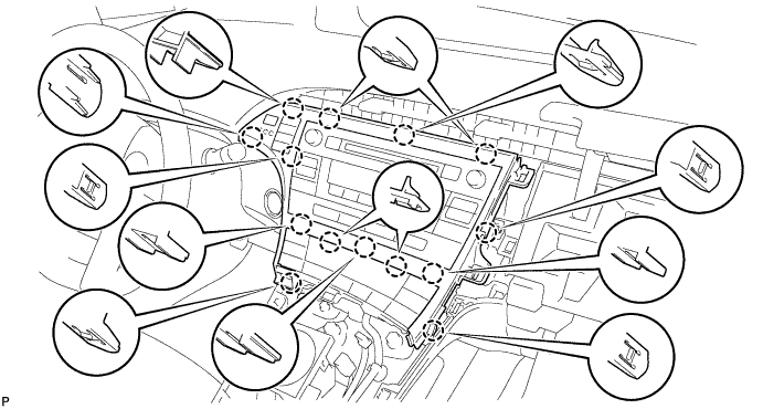
Engage the 5 claws as shown in the illustration.
-
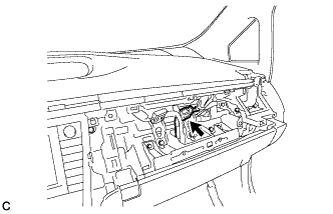
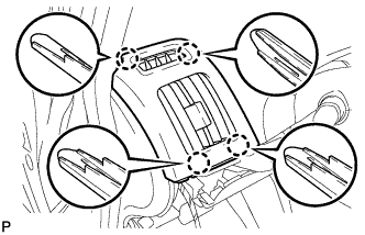
Engage the 2 claws and 4 clips, and install the upper instrument panel assembly as shown in the illustration.
-
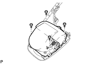
Install the 2 bolts <B>.
-
Install the 2 passenger airbag bolts <A>.
- Torque:
- 20 N*m { 204 kgf*cm, 15 ft.*lbf }
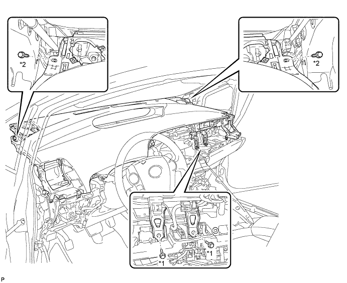
Text in Illustration *1 Passenger Airbag Bolt <A> *2 Bolt <B> -
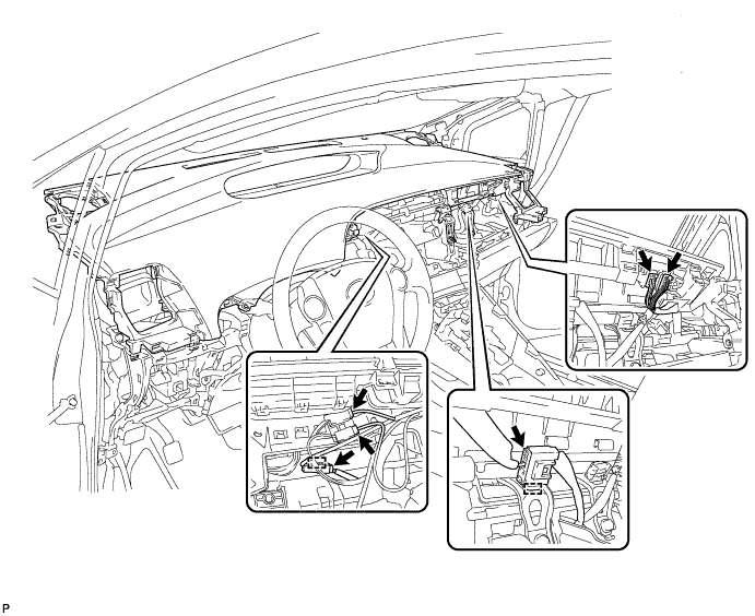
Engage the 2 clamps.
-
Connect each connector.
-
-
CONNECT NO. 3 INSTRUMENT PANEL WIRE
-
Check that the power switch is off.
-
Check that the cable is disconnected from the negative (-) battery terminal.
CAUTION:
Wait at least 90 seconds after disconnecting the cable from the negative (-) battery terminal to disable the SRS system.
-
Connect the connector.
Note
When connecting any airbag connector, take care not to damage the airbag wire harness.
-
-
INSTALL CENTER INSTRUMENT CLUSTER FINISH PANEL GARNISH
-
Connect the connector.
-
Engage the 7 claws.
-
Install the center instrument cluster finish panel garnish with the 2 screws <C>.
-
-
INSTALL INSTRUMENT CLUSTER FINISH PANEL END
-
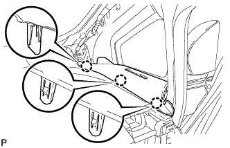
Engage the 2 guides and 5 claws to install the instrument cluster finish panel end as shown in the illustration.
-
-
INSTALL FRONT NO. 2 SPEAKER ASSEMBLY
Tech Tips
Use the same procedure for the RH side and LH side Click here.
-
INSTALL NO. 2 INSTRUMENT PANEL SPEAKER PANEL SUB-ASSEMBLY
-
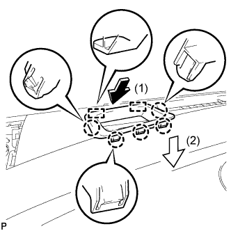
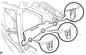
Engage the 2 guides and 6 claws to install the No. 2 instrument panel speaker panel sub-assembly as shown in the illustration.
-
-
INSTALL FRONT PILLAR GARNISH CORNER PIECE RH
-
Engage the 3 claws to install the front pillar garnish corner piece RH.
-
-
INSTALL FRONT PILLAR GARNISH RH
Tech Tips
Use the same procedure for the RH side and LH side Click here.
-
INSTALL FRONT NO. 2 SPEAKER ASSEMBLY
-
Connect the connector.
-
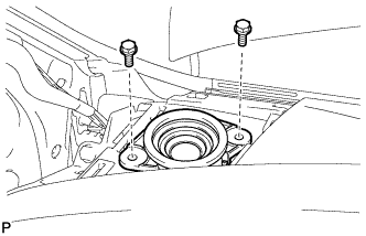
Install the front No. 2 speaker assembly with the 2 bolts.
-
-
INSTALL NO. 1 INSTRUMENT PANEL SPEAKER PANEL SUB-ASSEMBLY
-
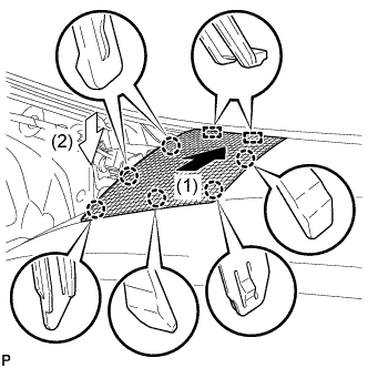
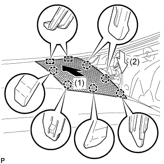
Engage the 2 guides and 6 claws to install the No. 1 instrument panel speaker panel sub-assembly as shown in the illustration.
-
-
INSTALL FRONT PILLAR GARNISH CORNER PIECE LH
-
Engage the 3 claws to install the front pillar garnish corner piece LH.
-
-
INSTALL FRONT PILLAR GARNISH LH
-
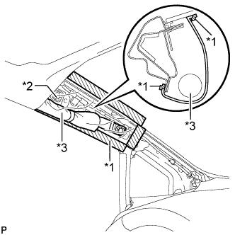
Text in Illustration *1 Adhesive Tape *2 Protective Cover *3 Curtain Shield Airbag Assembly Remove the protective cover.
-
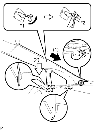
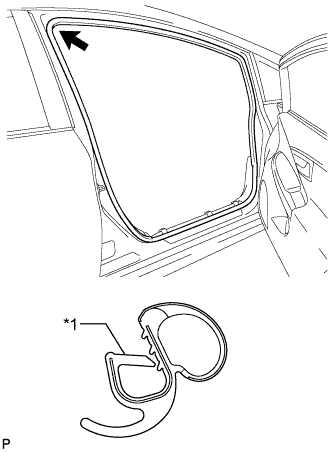
Text in Illustration *1 Front Pillar Garnish Clip *2 Protective Tape Make sure that the front pillar garnish clip is not damaged.
Note
-
If there is any damage, replace the garnish clip with a new one.
-
When a garnish clip is being replaced, make sure to install it in the direction shown in the illustration.
-
-
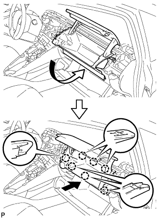
Engage the claw to direction indicated by the arrow (1).
-
Engage the 3 guides to direction indicated by the arrow (2).
-
Turn the end of the front pillar garnish clip 90° with needle-nosed pliers and install it to the front pillar garnish LH.
Tech Tips
Tape the needle-nosed pliers tip before use.
-
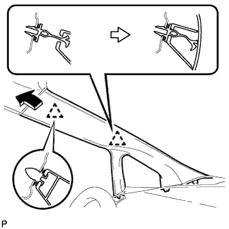
Engage 2 clips to install the front pillar garnish LH.
-
-
INSTALL INSTRUMENT PANEL FINISH PANEL END RH
-
Engage the guide as shown in the illustration.
-
Engage the guide as shown in the illustration.
-
Engage the 4 claws to install the instrument panel finish panel end RH.
-
-
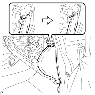
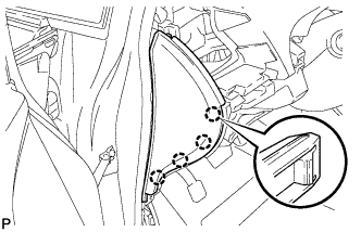
CONNECT FRONT DOOR OPENING TRIM WEATHERSTRIP RH
-
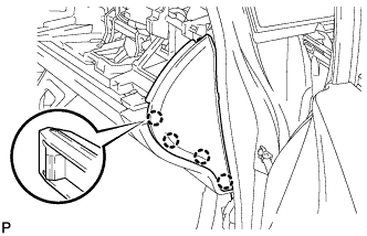
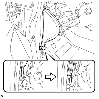
Text in Illustration *1 Alignment Mark (White) Align the alignment mark (White) on the weatherstrip with the protruding portion on the body indicated by the arrow in the illustration, and install the front door opening trim weatherstrip RH.
Note
After installation, check that the corners fit correctly.
-
-
INSTALL GLOVE COMPARTMENT DOOR
-
Open the glove compartment door assembly.
-
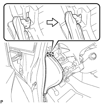
Insert the glove compartment door as shown in the illustration.
-
Engage the 7 claws to install the glove compartment door.
-
-
INSTALL NO. 2 INSTRUMENT PANEL REGISTER
-
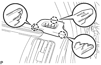
Engage the 3 claws and clip to install the No. 2 instrument panel register.
-
-
INSTALL NO. 1 SIDE DEFROSTER NOZZLE
-
Engage the 3 claws to install the No. 1 side defroster nozzle.
-
-
INSTALL INSTRUMENT PANEL FINISH PANEL END LH
-
Engage the guide as shown in the illustration.
-
Engage the guide as shown in the illustration.
-
Engage the 4 claws to install the instrument panel finish panel end LH.
-
-
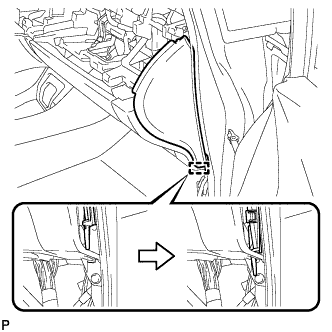
CONNECT FRONT DOOR OPENING TRIM WEATHERSTRIP LH
-
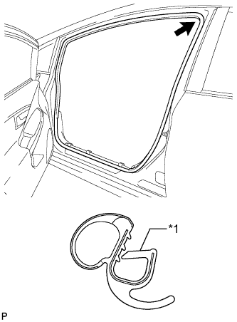
Text in Illustration *1 Alignment Mark (Yellow) Align the alignment mark (Yellow) on the weatherstrip with the protruding portion on the body indicated by the arrow in the illustration, and install the front door opening trim weatherstrip LH.
Note
After installation, check that the corners fit correctly.
-
-
INSTALL NO. 1 CENTER INSTRUMENT CLUSTER FINISH PANEL
-
Engage the 4 claws to install the No. 1 center instrument cluster finish panel.
-
-
INSTALL NO. 1 INSTRUMENT PANEL REGISTER
-
Engage the 4 claws to install the No. 1 instrument panel register.
-
-
INSTALL LOWER INSTRUMENT PANEL FINISH PANEL ASSEMBLY
-
Connect each connector.
-
Engage the clamp.
-
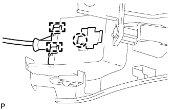
Engage the 2 guides and claw to connect the hood lock control cable.
-
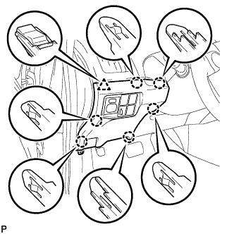
Engage the 6 claws and clip.
-
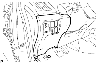
Install the lower instrument panel finish panel assembly with the screw <C>.
-
-
INSTALL COWL SIDE TRIM SUB-ASSEMBLY LH
-
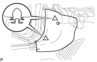
Engage the 2 clips.
-
Install the cowl side trim board LH with the clip.
-
-
INSTALL FRONT DOOR SCUFF PLATE LH
-
Engage the 10 claws to install the front door scuff plate LH.
-
-
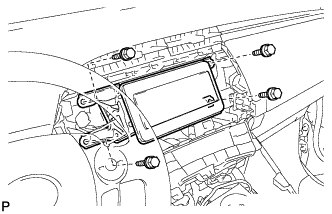
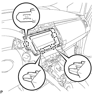
INSTALL NAVIGATION RECEIVER WITH BRACKET (w/ Navigation System)
-
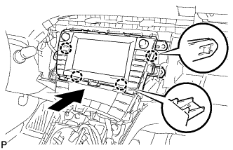
Engage the 4 claws to temporarily install the navigation receiver assembly with bracket as shown in the illustration.
-
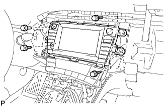
Install the navigation receiver assembly with bracket with the 4 bolts.
-
-
INSTALL RADIO RECEIVER WITH BRACKET (w/o Navigation System)
-
Connect each connector.
-
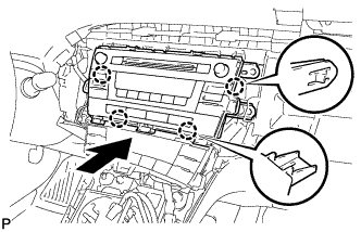
Engage the 4 claws as shown in the illustration.
-
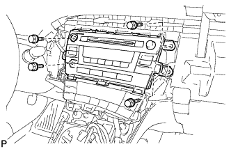
Install the radio receiver with bracket with the 4 bolts.
-
-
INSTALL RADIO TUNER OPENING COVER WITH BRACKET (w/o Radio Receiver)
-
Install the radio tuner opening cover with bracket with the 4 bolts <B>.
-
-
INSTALL CENTER INSTRUMENT CLUSTER FINISH PANEL SUB-ASSEMBLY (w/o Radio Receiver)
-
Engage the 4 claws to install the center instrument cluster finish panel sub-assembly.
-
-
INSTALL UPPER INSTRUMENT PANEL FINISH PANEL SUB-ASSEMBLY
-
Connect the connector.
-
Engage the 3 claws to install the upper instrument panel finish panel sub-assembly.
-
-
INSTALL INSTRUMENT CLUSTER FINISH PANEL GARNISH
-
Connect the connector.
-
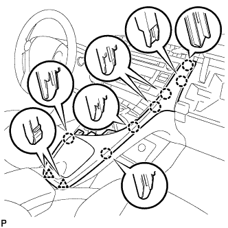
Engage the 14 claws to install the instrument cluster finish panel garnish.
-
-
INSTALL INSTRUMENT PANEL CUP HOLDER ASSEMBLY
-
Install the instrument panel cup holder with the 4 screws <C> to the lower center instrument cluster finish panel sub-assembly.
-
-
INSTALL LOWER CENTER INSTRUMENT CLUSTER FINISH PANEL SUB-ASSEMBLY
-
Engage the 7 claws and 2 clips to install the lower center instrument cluster finish panel sub-assembly.
-
-
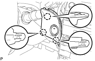
INSTALL INTEGRATION CONTROL AND PANEL ASSEMBLY
-
Connect each connector.
-
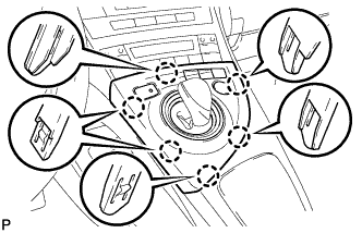
Engage the 6 claws to install the integration control and panel assembly.
-
-
CONNECT CABLE TO NEGATIVE BATTERY TERMINAL
Note
When disconnecting the cable, some systems need to be initialized after the cable is reconnected Click here.
-
INSTALL REAR NO. 3 FLOOR BOARD
-

Engage the 2 guides to install the rear No. 3 floor board.
-
-
INSTALL REAR DECK FLOOR BOX
-
Install the rear deck floor box.
-
-
INSTALL REAR NO. 2 FLOOR BOARD
-

Engage the 3 guides <A>.
-
Engage the 2 guides <B> and install the rear No. 2 floor board as shown in the illustration.
-
-
INSPECT SRS WARNING LIGHT
-
Inspect the SRS warning light Click here.
-