SOLAR VENTILATION ECU REMOVAL

-
PRECAUTION (w/ Navigation System for HDD)
Note
After the power switch is turned off, the display and navigation module display (HDD navigation system) records various types of memory and settings. As a result, after turning the power switch off, make sure to wait at least 60 seconds before disconnecting the cable from the negative (-) battery terminal.
-
REMOVE REAR NO. 2 FLOOR BOARD
-

Disengage the 2 guides <A> as shown in the illustration.
-
Disengage the 3 guides <B> and remove the rear No. 2 floor board.
-
-
REMOVE REAR DECK FLOOR BOX
-
Remove the rear deck floor box.
-
-
REMOVE REAR NO. 3 FLOOR BOARD
-

Disengage the 2 guides and remove the rear No. 3 floor board.
-
-
DISCONNECT CABLE FROM NEGATIVE BATTERY TERMINAL
Note
When disconnecting the cable, some systems need to be initialized after the cable is reconnected Click here.
-
REMOVE INTEGRATION CONTROL AND PANEL ASSEMBLY
-
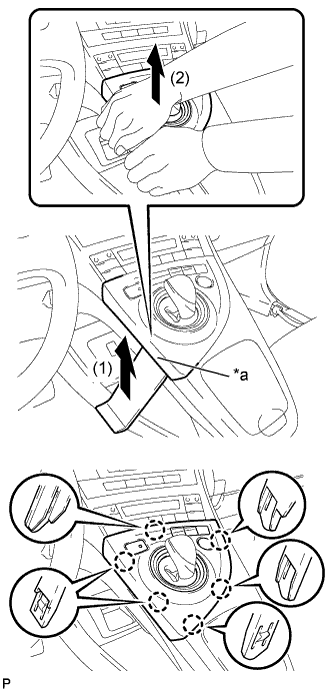
Text in Illustration *a Lift slightly Using a moulding remover, slightly lift the panel at the position shown in the illustration.
-
Pull the integration control and panel assembly in the direction indicated by the arrow to disengage the 6 claws.
-
Disconnect each connector and remove the integration control and panel assembly.
-
-
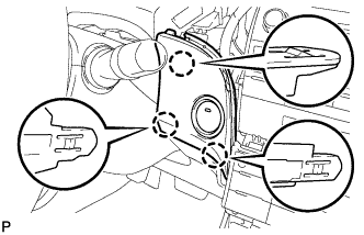
REMOVE LOWER CENTER INSTRUMENT CLUSTER FINISH PANEL SUB-ASSEMBLY
-
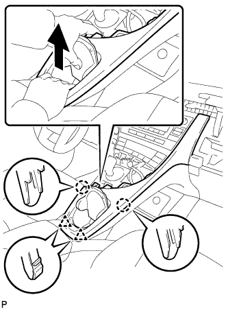
Pull the lower center instrument cluster finish panel sub-assembly in the direction indicated by the arrow to disengage the 2 claws and 2 clips.
-
Pull the lower center instrument cluster finish panel sub-assembly in the direction indicated by the arrow to disengage the 5 claws and remove the lower center instrument cluster finish panel sub-assembly.
-
-
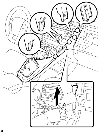
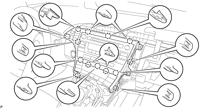
REMOVE INSTRUMENT CLUSTER FINISH PANEL GARNISH
-
Disengage the 14 claws.
-
Disconnect the connector and remove the instrument cluster finish panel garnish.
-
-
REMOVE UPPER INSTRUMENT PANEL FINISH PANEL SUB-ASSEMBLY
-
Disengage the 3 claws.
-
Disconnect the connector and remove the upper instrument panel finish panel sub-assembly.
-
-
REMOVE CENTER INSTRUMENT CLUSTER FINISH PANEL SUB-ASSEMBLY (w/o Radio Receiver)
-
Disengage the 4 claws and remove the center instrument cluster finish panel sub-assembly.
-
-
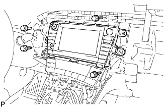
REMOVE RADIO TUNER OPENING COVER WITH BRACKET (w/o Radio Receiver)
-
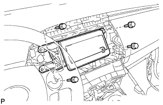
Remove the 4 bolts <B> and radio tuner opening cover with bracket.
-
-
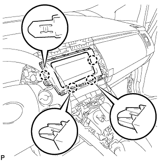
REMOVE RADIO AND DISPLAY RECEIVER ASSEMBLY WITH BRACKET (for Radio and Display Type)
-
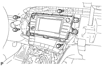
Remove the 4 bolts.
-
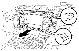
Disengage the 4 claws as shown in the illustration.
-
Disconnect each connector and remove the radio and display receiver assembly with bracket.
-
-
REMOVE NAVIGATION RECEIVER WITH BRACKET (for Navigation Receiver Type)
-
Remove the 4 bolts.
-
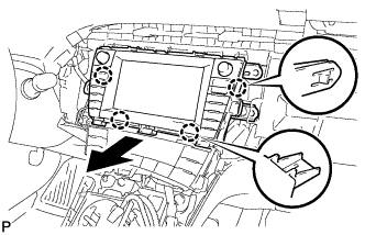
Disengage the 4 claws and remove the navigation receiver with bracket as shown in the illustration.
-
Disconnect each connector.
-
-
REMOVE AIR CONDITIONING CONTROL ASSEMBLY
-
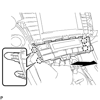
Disengage the 4 claws and remove the air conditioning control assembly as shown in the illustration.
-
Disconnect the connector.
Note
Since the connectors for the air conditioning control assembly and the integration control and panel sub-assembly are the same shape, mark them so that they will not be reconnected incorrectly.
-
-
REMOVE SOLAR VENTILATION ECU
-
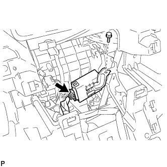
Remove the bolt.
-
Disconnect the connector to remove the solar ventilation ECU.
-