LOWER INSTRUMENT PANEL INSTALLATION

-
INSTALL LOWER INSTRUMENT PANEL SUB-ASSEMBLY (for LHD)
-
When using a new lower instrument panel sub-assembly:
-
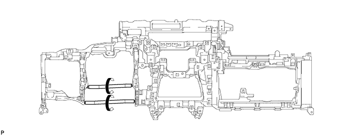
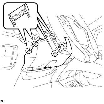
Immediately before installing the lower instrument panel sub-assembly, twist and cut off the portions shown in the illustration.
-
-
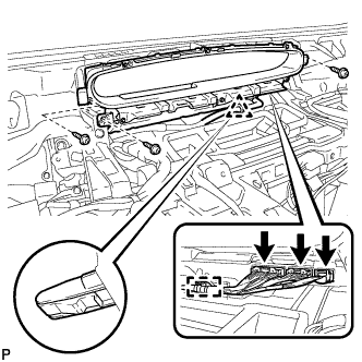
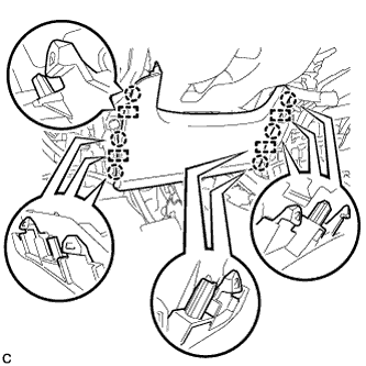
Install the lower instrument panel sub-assembly with the 4 bolts <B>, 11 bolts <C> and screw <D>.
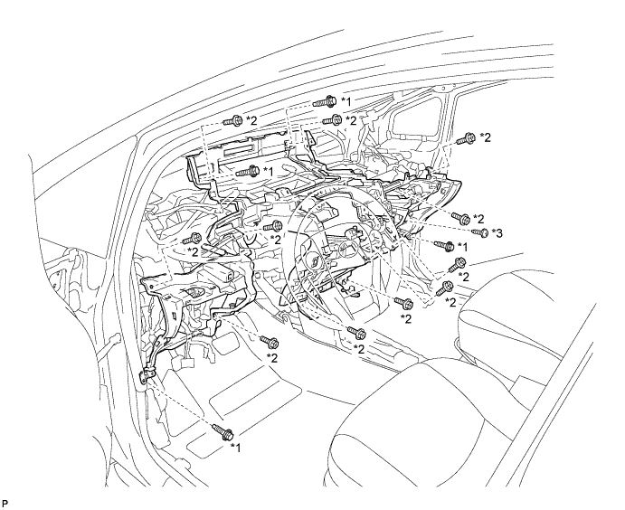
Text in Illustration *1 Bolt <B> *2 Bolt <C> *3 Screw <D> - - -
Engage each clamp.
-
-
INSTALL LOWER INSTRUMENT PANEL SUB-ASSEMBLY (for RHD)
-
When using a new lower instrument panel sub-assembly:
-
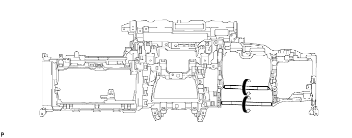
Immediately before installing the lower instrument panel sub-assembly, twist and cut off the portions shown in the illustration.
-
-
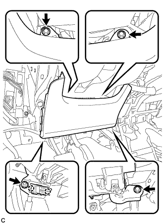
Install the lower instrument panel sub-assembly with the 4 bolts <B>, 11 bolts <C> and screw <D>.
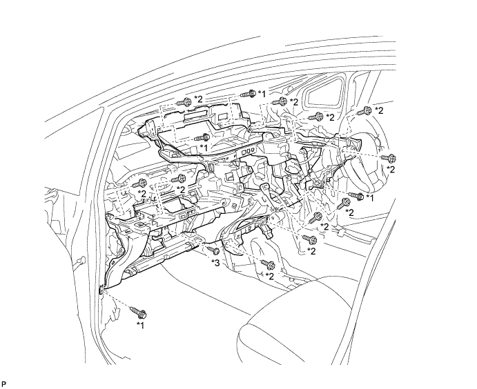
Text in Illustration *1 Bolt <B> *2 Bolt <C> *3 Screw <D> - - -
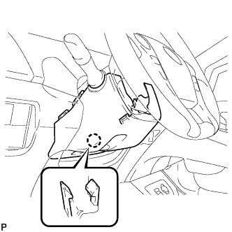
Engage each clamp.
-
Engage the 2 claws.
-
-
INSTALL NO. 2 ANTENNA CORD SUB-ASSEMBLY (for LHD)
-
for Plug Type Antenna Cord:
-
Engage the 4 clamps.
-
Install the No. 2 antenna cord sub-assembly with the bolt.
-
Connect the 2 connectors.
-
-
for Connector Type Antenna Cord:
-
Engage the 4 clamps.
-
Install the No. 2 antenna cord sub-assembly with the bolt.
-
Connect the connector.
-
-
w/ Digital Audio Broadcasting Antenna:
-
Engage the 5 clamps.
-
Install the No. 2 antenna cord sub-assembly with the bolt.
-
Connect the 2 connectors.
-
-
-
INSTALL NO. 2 ANTENNA CORD SUB-ASSEMBLY (for RHD)
-
Plug Type Antenna Cord:
-
Engage the 5 clamps.
-
Install the No. 2 antenna cord sub-assembly with the bolt.
-
Connect the 2 connectors.
-
-
for Connector Type Antenna Cord:
-
Engage the 5 clamps.
-
Install the No. 2 antenna cord sub-assembly with the bolt.
-
Connect the connector.
-
-
w/ Digital Audio Broadcasting Antenna:
-
Engage the 6 clamps.
-
Install the No. 2 antenna cord sub-assembly with the bolt.
-
Connect the 2 connectors.
-
-
-
INSTALL GLOVE BOX LIGHT ASSEMBLY
-
Engage the 2 claws and install the glove box light assembly.
-
Connect the connector.
-
-
INSTALL GLOVE COMPARTMENT DOOR LOCK ASSEMBLY
-
Engage the claw and guide.
-
Install the glove compartment door lock assembly with the screw <E>.
-
-
INSTALL POWER STEERING ECU ASSEMBLY
-
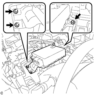
Install the power steering ECU assembly with the bolt and 2 nuts.
- Torque:
- 8.0 N*m { 82 kgf*cm, 71 in.*lbf }
-
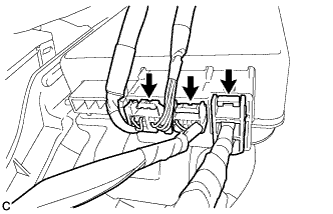
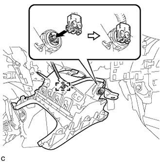
Connect the 3 connectors to the power steering ECU assembly.
-
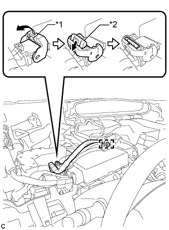
Text in Illustration *1 Lock Lever *2 Lock of the Lock Lever Connect the connector to the power steering ECU assembly.
Tech Tips
As shown in the illustration, return the lock lever to its original position to connect the connector and securely push in the lock of the lock lever.
-
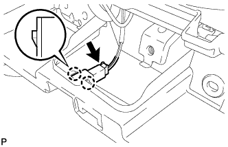
Engage the wire harness clamp to the power steering ECU assembly.
-
-
INSTALL COMBINATION METER ASSEMBLY
-
Engage the clip.
-
Install the combination meter assembly with the 3 screws.
-
Engage the clamp.
-
Connect the 3 connectors.
-
-
INSTALL NO. 1 HEATER TO REGISTER DUCT
-
Install the No. 1 heater to register duct with the 3 clips.
-
-
INSTALL COWL SIDE TRIM SUB-ASSEMBLY RH
Tech Tips
Use the same procedure for the RH side and LH side Click here.
-
INSTALL FRONT DOOR SCUFF PLATE RH
Tech Tips
Use the same procedure for the RH side and LH side Click here.
-
INSTALL GLOVE COMPARTMENT DOOR STOPPER SUB-ASSEMBLY
-
Engage the claw to install the glove compartment door stopper sub-assembly.
-
-
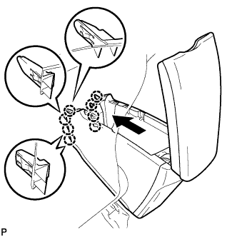
INSTALL GLOVE COMPARTMENT DOOR ASSEMBLY
-
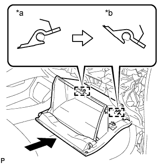
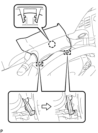
Text in Illustration *a Opened Approximately 55° *b Closed With the glove compartment door assembly opened approximately 55° from its closed position, engage the 2 hinges horizontally.
Note
Engaging the hinges from the top will deform the hinges. Be sure to install the glove compartment door assembly horizontally.
-
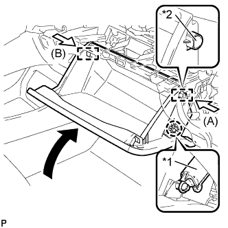
Text in Illustration *1 Glove Compartment Door Stopper Sub-assembly *2 Stopper Slightly bend the stoppers (A) and (B) in the directions indicated by the arrows in the illustration and engage the stoppers to install the glove compartment door assembly.
-
Engage the claw and connect the glove compartment door stopper sub-assembly.
-
-
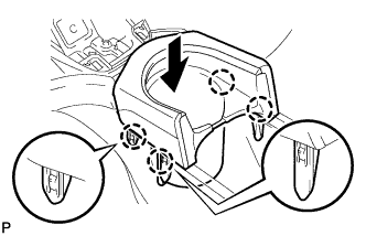
INSTALL NO. 2 INSTRUMENT PANEL UNDER COVER SUB-ASSEMBLY
-
Connect the connector.
-
Engage the guide and 3 claws to install the No. 2 instrument panel under cover sub-assembly.
-
-
INSTALL DRIVER SIDE KNEE AIRBAG ASSEMBLY
-
Check that the power switch is off.
-
Check that the cable is disconnected from the negative (-) battery terminal.
CAUTION:
Wait at least 90 seconds after disconnecting the cable from the negative (-) battery terminal to disable the SRS system.
-
Connect the airbag connector and install the clamp to the driver side knee airbag assembly.
Note
When connecting any airbag connector, take care not to damage the airbag wire harness.
-
Push in the lock to install the airbag connector.
-
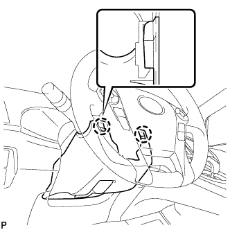
Temporarily install the driver side knee airbag assembly with the 6 claws and 4 guides.
-
Install the driver side knee airbag assembly with the 4 bolts.
- Torque:
- 10 N*m { 102 kgf*cm, 7 ft.*lbf }
Note
Confirm that the driver side knee airbag assembly is installed securely without any excessive gaps and is not protruding outward.
-
-
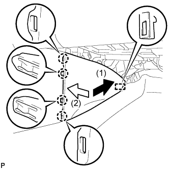
INSTALL NO. 1 INSTRUMENT PANEL UNDER COVER SUB-ASSEMBLY (for LHD)
-
Connect each connector.
-
Engage the guide and claw.
-
Install the No. 1 instrument panel under cover sub-assembly with the 2 screws <D>.
-
-
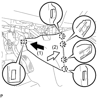
INSTALL NO. 1 INSTRUMENT PANEL UNDER COVER SUB-ASSEMBLY (for RHD)
-
Connect each connector.
-
Engage the guide and 2 claws.
-
Install the No. 1 instrument panel under cover sub-assembly with the screw <D>.
-
-
INSTALL UPPER STEERING COLUMN COVER
-
Engage the claw and 2 pins to install the upper steering column cover.
-
-
INSTALL LOWER STEERING COLUMN COVER
Note
If the lower steering column cover is installed in the incorrect order, it will not be possible to assemble the lower steering column cover.
-
Engage the 2 claws to install the lower steering column cover.
-
Engage the 4 claws.
-
Engage the claw.
Tech Tips
Press the area around the claw to engage it.
-
-
INSTALL NO. 1 SWITCH HOLE BASE
-
Connect the connector.
-
Engage the 5 claws to install the No. 1 switch hole base.
-
-
INSTALL UPPER INSTRUMENT PANEL FINISH PANEL ASSEMBLY
-
Temporarily install the console box assembly.
-

Engage the 9 claws as shown in the illustration.
-
Install the to install the upper instrument panel finish panel assembly with the 2 bolts <A>.
-
Engage the clamp.
-
-
INSTALL SHIFT LOCK CONTROL UNIT ASSEMBLY
-
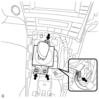
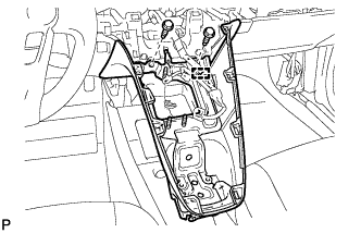
Install the shift lock control unit assembly with the 3 nuts.
- Torque:
- 12 N*m { 122 kgf*cm, 9 ft.*lbf }
-
Connect the connector to the shift lock control unit assembly.
-
-
INSTALL AIR CONDITIONING CONTROL ASSEMBLY
-
Connect the connector.
Note
Since the connectors for the air conditioning control assembly and the integration control and panel sub-assembly are the same shape, take care to connect each connector to the correct component.
-
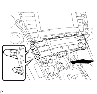
Engage the 4 claws to install the air conditioning control assembly.
-
-
INSTALL CONSOLE BOX ASSEMBLY
-
Connect each connector.
-
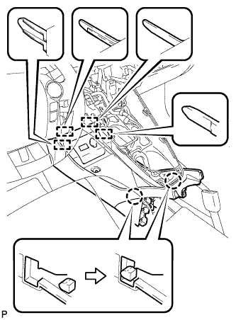
Engage the 4 guides and 2 claws as shown in the illustration.
-
Install the console box assembly with the bolt <B> and 2 clips.
-
-
INSTALL BOX BOTTOM MAT
-
Engage the fastener to install the box bottom mat.
-
-
INSTALL FRONT NO. 2 CONSOLE BOX INSERT
-
Engage the guide and 4 claws to install the front No. 2 console box insert as shown in the illustration.
-
-
INSTALL FRONT NO. 1 CONSOLE BOX INSERT
-
Engage the guide and 4 claws to install the front No. 1 console box insert as shown in the illustration.
-
-
INSTALL NO. 2 CONSOLE BOX MOUNTING BRACKET
-
Install the No. 2 console box mounting bracket with the 6 bolts <B>.
-
-
INSTALL ELECTRICAL KEY OSCILLATOR
-
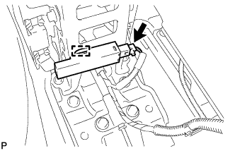
Engage the clamp and install the electrical key oscillator.
Note
Be careful when installing the electrical key oscillator. If the oscillator is dropped, replace it with a new one.
-
Connect the connector.
-
-
INSTALL REAR CONSOLE BOX ASSEMBLY
-
Connect each connector.
-
Engage the 8 claws as shown in the illustration.
-
Install the rear console box assembly with the 5 bolts.
-
-
INSTALL CONSOLE BOX CARPET
-
Install the console box carpet.
-
-
INSTALL REAR CONSOLE BOX CUP HOLDER
-
Engage the 4 claws to install the rear console box cup holder as shown in the illustration.
-
-
INSTALL UPPER INSTRUMENT PANEL ASSEMBLY
-
INSPECT SHIFT LEVER
-
Turn the power switch on (READY).
-
Check that all available shift positions can be selected moving the shift lever.
Tech Tips
After the shift lever is replaced with a new one, perform the above operation. If this operation is not performed, moving the shift lever may not initially select shift positions.
-