ROOM TEMPERATURE SENSOR REMOVAL

-
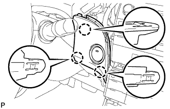
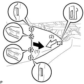
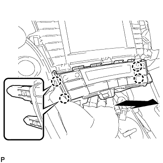
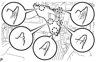
REMOVE INTEGRATION CONTROL AND PANEL ASSEMBLY
-
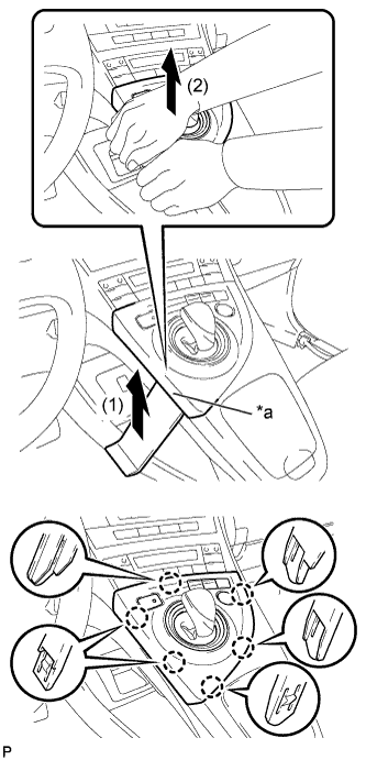
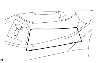
Text in Illustration *a Lift slightly Using a moulding remover, slightly lift the panel at the position shown in the illustration.
-
Pull the integration control and panel assembly in the direction indicated by the arrow to disengage the 6 claws.
-
Disconnect each connector and remove the integration control and panel assembly.
-
-
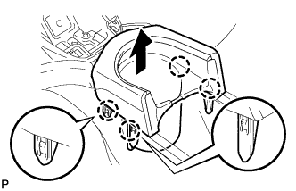
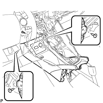
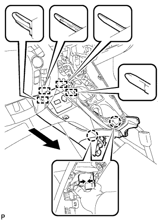
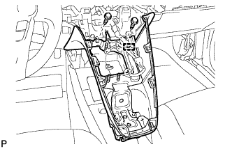
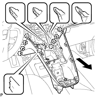
REMOVE LOWER CENTER INSTRUMENT CLUSTER FINISH PANEL SUB-ASSEMBLY
-
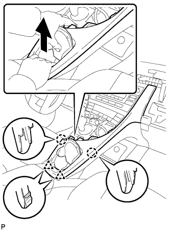
Pull the lower center instrument cluster finish panel sub-assembly in the direction indicated by the arrow to disengage the 2 claws and 2 clips.
-
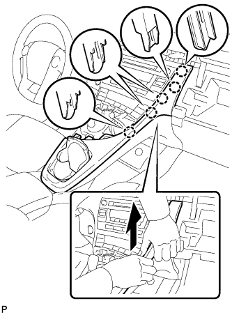
Pull the lower center instrument cluster finish panel sub-assembly in the direction indicated by the arrow to disengage the 5 claws and remove the lower center instrument cluster finish panel sub-assembly.
-
-
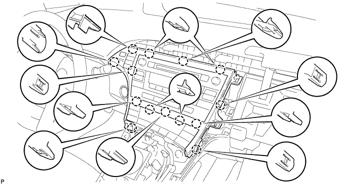
REMOVE INSTRUMENT CLUSTER FINISH PANEL GARNISH
-
Disengage the 14 claws.
-
Disconnect the connector and remove the instrument cluster finish panel garnish.
-
-
REMOVE UPPER INSTRUMENT PANEL FINISH PANEL SUB-ASSEMBLY
-
Disengage the 3 claws.
-
Disconnect the connector and remove the upper instrument panel finish panel sub-assembly.
-
-
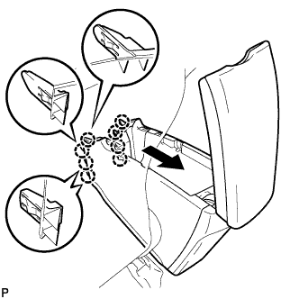
REMOVE REAR CONSOLE BOX CUP HOLDER
-
Disengage the 4 claws and remove the rear console box cup holder as shown in the illustration.
-
-
REMOVE CONSOLE BOX CARPET
-
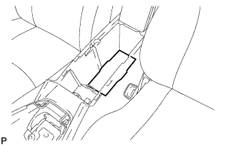
Remove the console box carpet.
-
-
REMOVE REAR CONSOLE BOX ASSEMBLY
-
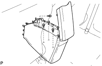
Remove the 5 bolts.
-
Pull the rear console box assembly in the direction indicated by the arrow to disengage the 8 claws.
-
Disconnect each connector and remove the rear console box assembly.
-
-
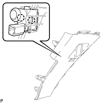
REMOVE ELECTRICAL KEY OSCILLATOR
-
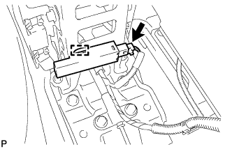
Disconnect the connector.
-
Disengage the clamp and remove the electrical key oscillator.
Note
Be careful when removing the electrical key oscillator. If the oscillator is dropped, replace it with a new one.
-
-
REMOVE NO. 2 CONSOLE BOX MOUNTING BRACKET
-
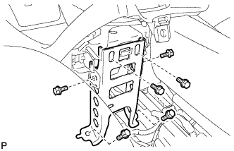
Remove the 6 bolts <B> and No. 2 console box mounting bracket.
-
-
REMOVE FRONT NO. 1 CONSOLE BOX INSERT
-
Pull the front No. 1 console box insert in the direction indicated by the arrow to disengage the 4 claws and guide, and remove the front No. 1 console box insert.
-
-
REMOVE FRONT NO. 2 CONSOLE BOX INSERT
-
Pull the front No. 2 console box insert in the direction indicated by the arrow to disengage the 4 claws and guide, and remove the front No. 2 console box insert.
-
-
REMOVE BOX BOTTOM MAT
-
Disengage the fastener and remove the box bottom mat.
-
-
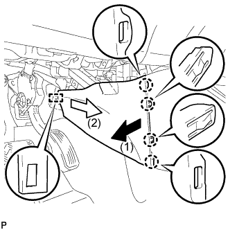
SEPARATE CONSOLE BOX ASSEMBLY
-
Remove the bolt <B> and 2 clips.
-
While pushing the parts shown in the illustration inward, pull the console box assembly in the direction indicated by the arrow to disengage the 2 claws and 4 guides.
-
Disconnect the connector and separate the console box assembly.
-
-
REMOVE AIR CONDITIONING CONTROL ASSEMBLY
-
Disengage the 4 claws and remove the air conditioning control assembly as shown in the illustration.
-
Disconnect the connector.
Note
Since the connectors for the air conditioning control assembly and the integration control and panel sub-assembly are the same shape, mark them so that they will not be reconnected incorrectly.
-
-
REMOVE SHIFT LOCK CONTROL UNIT ASSEMBLY
-
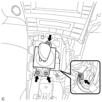
Disconnect the connector from the shift lock control unit assembly.
-
Remove the 3 nuts and shift lock control unit assembly.
-
-
REMOVE UPPER INSTRUMENT PANEL FINISH PANEL ASSEMBLY
-
Disengage the clamp.
-
Remove the 2 bolts <A>.
-
Pull the upper instrument panel finish panel assembly in the direction indicated by the arrow to disengage the 9 claws and remove the upper instrument panel finish panel assembly.
-
-
REMOVE NO. 1 SWITCH HOLE BASE
-
Disengage the 5 claws.
-
Disconnect the connector to remove the No. 1 switch hole base.
-
-
REMOVE ROOM TEMPERATURE SENSOR
-
Disengage the 2 claws and remove the room temperature sensor from the No. 1 switch hole base.
-