AIR CONDITIONING UNIT INSTALLATION

-
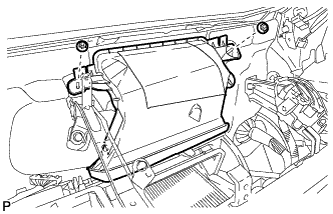
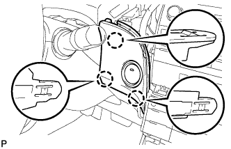
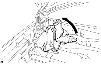
TEMPORARILY TIGHTEN AIR CONDITIONING UNIT ASSEMBLY
Note
-
Be sure to support the air conditioning unit assembly when removing it because failure to do so may cause the bracket of the air conditioning unit assembly to break.
-
When installing the air conditioning unit, eliminate static electricity by touching the vehicle body to prevent the components from being damaged.
-
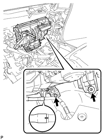
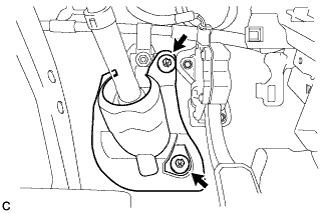
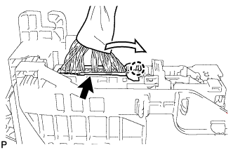
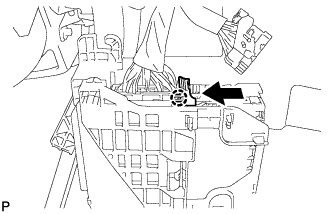
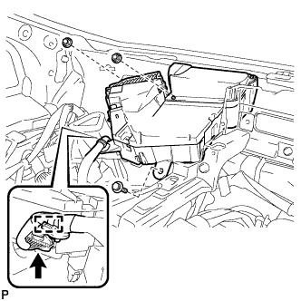
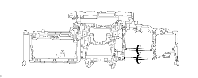
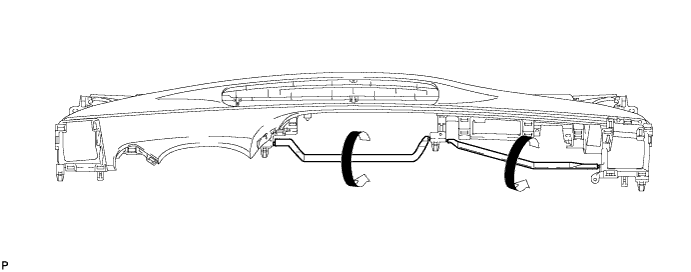
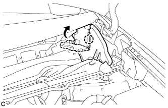
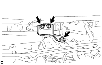
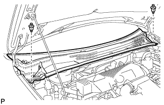
Temporarily tighten the air conditioning unit assembly with the bolt and the nut.
-
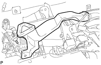
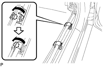
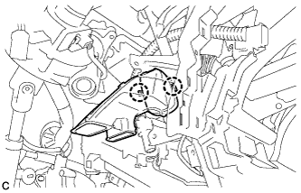
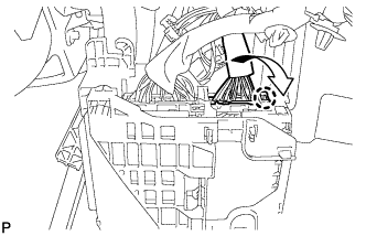
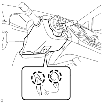
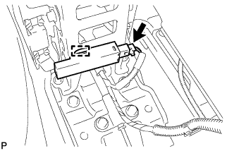
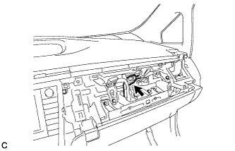
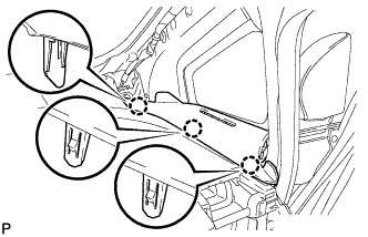
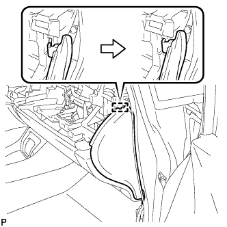
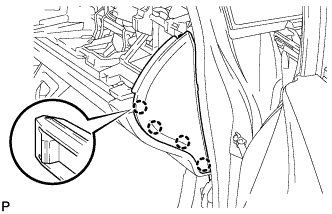
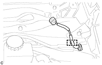
Engage the the cooler drain hose as shown in the illustration.
Note
Connect the cooler drain hose firmly to prevent water leaks.
-
-
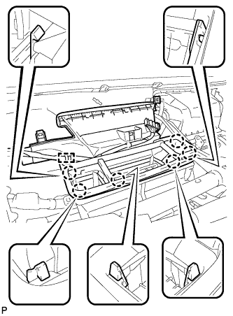
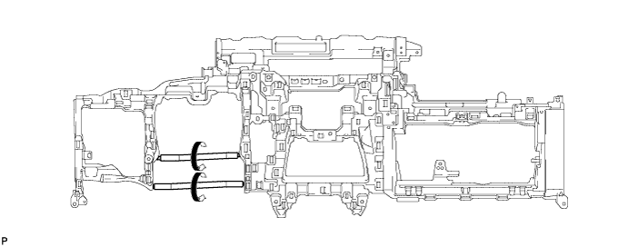
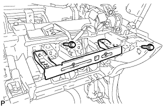
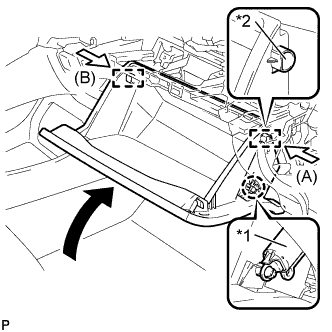
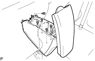
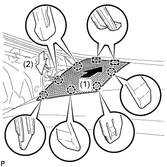
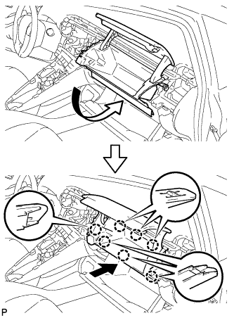
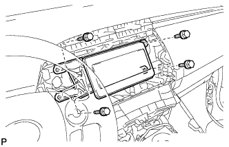
INSTALL INSTRUMENT PANEL REINFORCEMENT ASSEMBLY
-
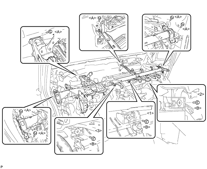
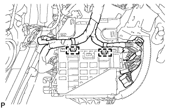
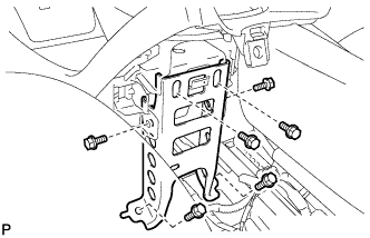
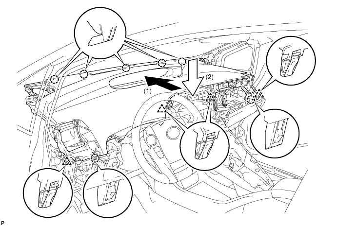
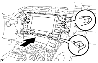
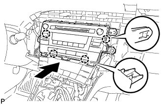
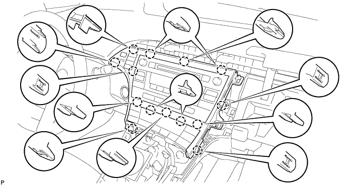
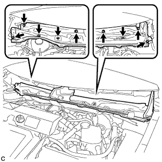
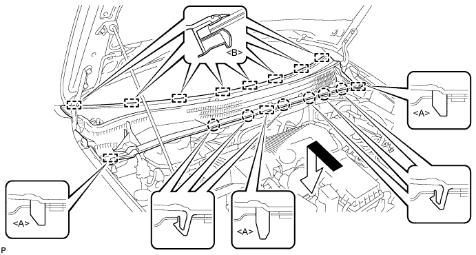
Install the instrument panel reinforcement assembly with the 6 bolts <A>.
-
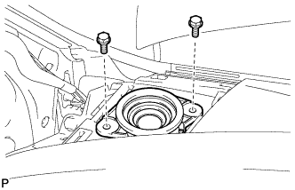
Install the air conditioning unit assembly with the 3 bolts <B>
- Torque:
- Torque: <B>
- 9.8 N*m { 100 kgf*cm, 87 in.*lbf }
Tech Tips
Tighten the bolts in the order shown in the illustration.
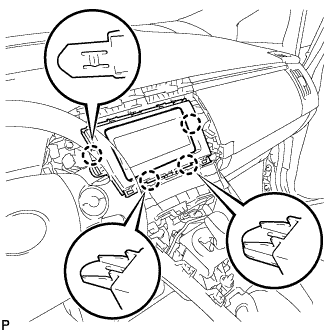
-
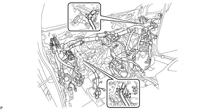
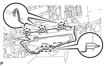
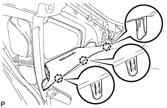
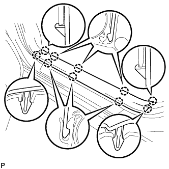
Engage each clamp.
-
-
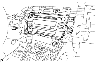
INSTALL AIR CONDITIONING UNIT ASSEMBLY
-
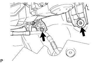
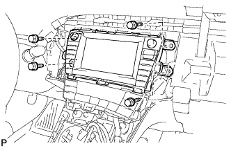
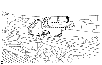
Install the air conditioning unit with the nut assembly with the bolt and nut.
- Torque:
- Bolt
- 9.8 N*m { 100 kgf*cm, 87 in.*lbf }
- Nut
- 9.8 N*m { 100 kgf*cm, 87 in.*lbf }
-
-
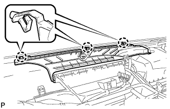
INSTALL NO. 3 AIR DUCT SUB-ASSEMBLY
-
Install the No. 3 air duct sub-assembly with the 2 nuts.
- Torque:
- 9.8 N*m { 100 kgf*cm, 87 in.*lbf }
-
-
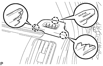
INSTALL LOWER DEFROSTER NOZZLE ASSEMBLY
-
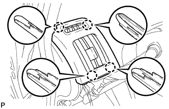
Engage the 6 claws and remove the lower defroster nozzle assembly.
-
Engage the clamp.
-
-
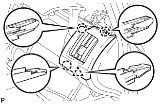
INSTALL DEFROSTER NOZZLE ASSEMBLY
-
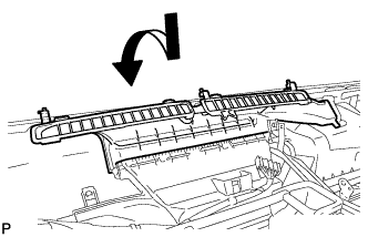
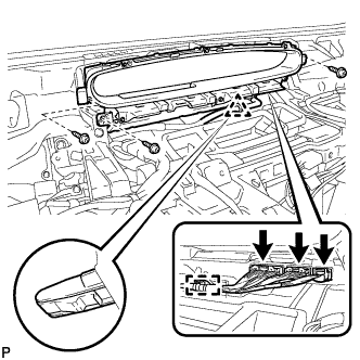
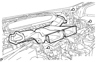
Install the defroster nozzle assembly as shown in the illustration.
-
Engage the 3 claws.
-
-
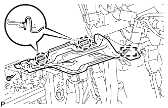
INSTALL NO. 2 INSTRUMENT PANEL BRACE SUB-ASSEMBLY
-
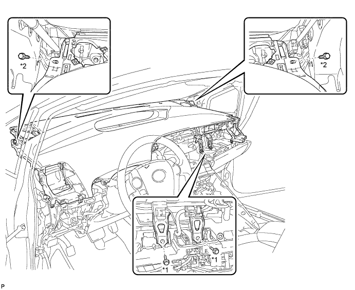
Install the No. 2 instrument panel brace sub-assembly with the screw.
- Torque:
- 4.0 N*m { 41 kgf*cm, 35 in.*lbf }
-
Install the bolt and nut.
-
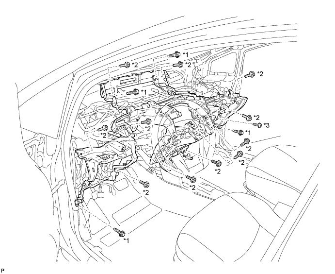
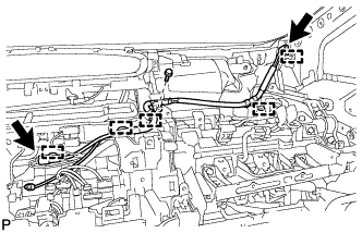
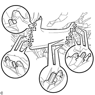
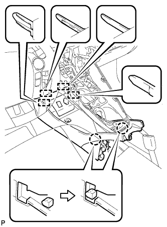
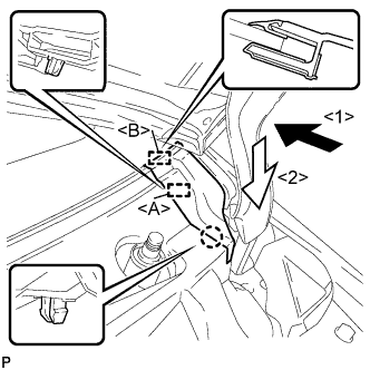
Install the screw <B> and 2 nuts to the computer integration box RH.
-
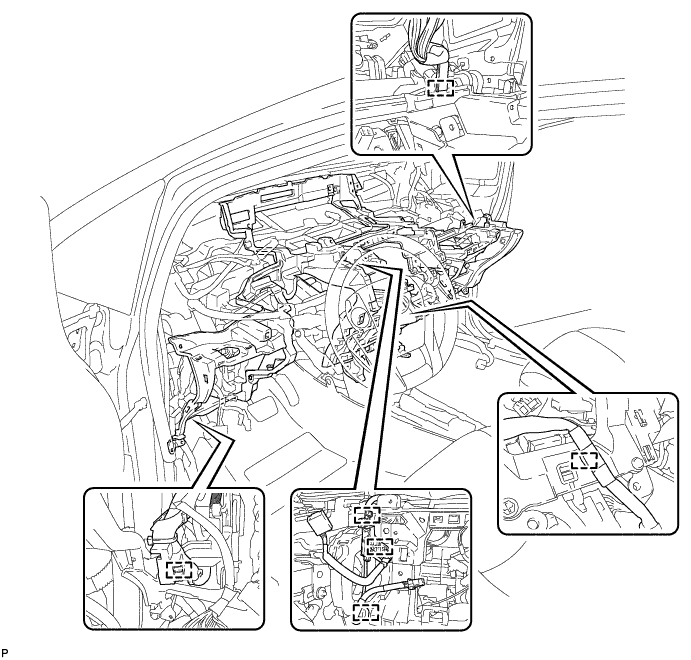
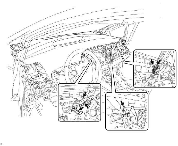
Engage each clamp.
-
Connect each connector.
-
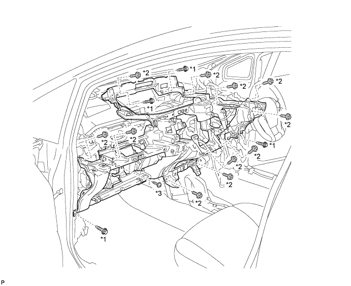
Install the 3 screws <A>.
-
Install the bolt and connect the earth wire.
- Torque:
- 8.4 N*m { 86 kgf*cm, 74 in.*lbf }
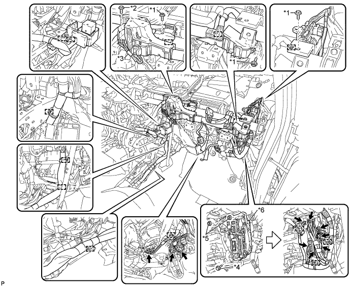
Text in Illustration *1 Screw <A> *2 Bolt *3 Earth wires *4 Screw <B> *5 Nut *6 Computer integration box RH
-
-
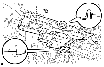
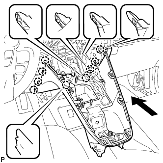
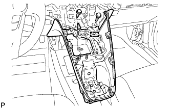
INSTALL NO. 1 INSTRUMENT PANEL BRACE SUB-ASSEMBLY
-
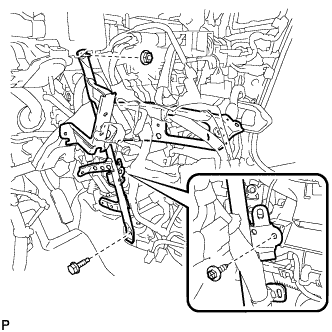
Install the No. 1 instrument panel brace sub-assembly with the screw.
- Torque:
- 4.0 N*m { 41 kgf*cm, 35 in.*lbf }
-
Install the bolt and nut.
-
Check that the power switch is off.
-
Check that the cable is disconnected from the negative (-) battery terminal.
CAUTION:
Wait at least 90 seconds after disconnecting the cable from the negative (-) battery terminal to disable the SRS system.
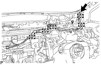
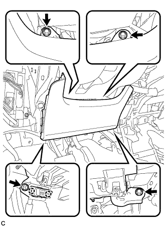
-
Connect the center airbag sensor connectors to the center airbag sensor assembly as shown in the illustration.
Note
When connecting any airbag connector, take care not to damage the airbag wire harness.
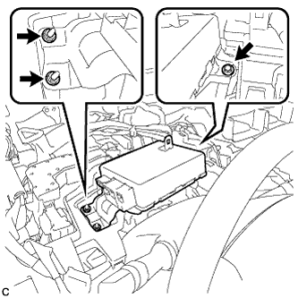
-
Check that the waterproof sheet on the top of the center airbag sensor is not folded or deformed.
-
Check that there is no looseness in the installation parts of the center airbag sensor assembly.
-
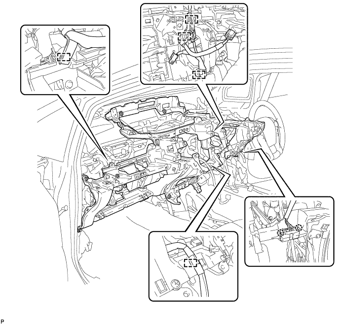
Connect each connector.
-
Engage each clamp and claw.
-
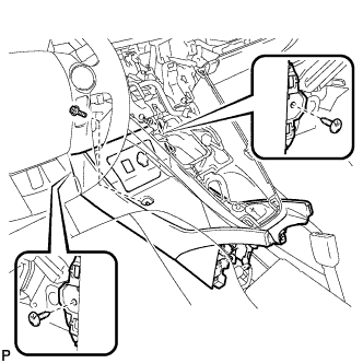
Install the screw.
-
Install the 2 bolts and connect the 2 earth wires.
- Torque:
- 8.4 N*m { 86 kgf*cm, 74 in.*lbf }
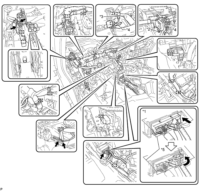
Text in Illustration *1 Center airbag sensor connector *2 Screw *3 Bolt *4 Earth wires *5 Waterproof Sheet - -
-
-
INSTALL NO. 3 SIDE DEFROSTER NOZZLE DUCT
-
Install the No. 3 side defroster nozzle duct with the clip.
-
-
INSTALL REAR NO. 1 AIR DUCT
-
Engage the 4 claws to install the rear No. 1 air duct.
-
-
INSTALL REAR NO. 3 AIR DUCT
-
Engage the 2 claws to install the rear No. 3 air duct.
-
Engage the 2 claws and install the clip.
-
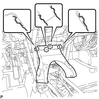
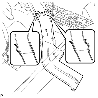
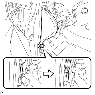
Engage the fastener to install the floor carpet to the original position as shown in the illustration.
Text in Illustration *1 Fastener -
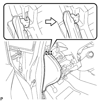
Engage each claw to close the door scuff plate clamps as shown in the illustration.
-
-
INSTALL REAR NO. 2 AIR DUCT
-
Engage the 2 claws to install the rear No. 2 air duct.
-
Engage the 2 claws and install the clip.
-
Engage the fastener to install the floor carpet to the original position as shown in the illustration.
Text in Illustration *1 Fastener -
Engage each claw to close the door scuff plate clamps as shown in the illustration.
-
-
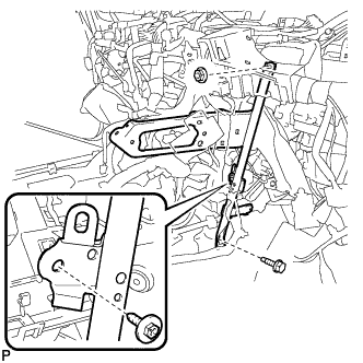
INSTALL STEERING POST ASSEMBLY
-
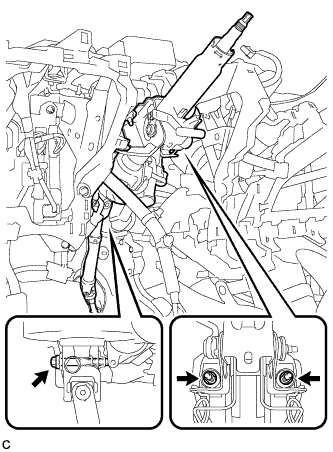
Install the steering post assembly with the bolt and 2 nuts.
- Torque:
- Bolt
- 36 N*m { 367 kgf*cm, 27 ft.*lbf }
- Nut
- 25 N*m { 255 kgf*cm, 18 ft.*lbf }
Note
There are two different bolt sizes (12 mm (0.472 in.) or 14 mm (0.551 in.)) available.
-
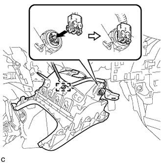
Connect the connectors and engage the wire harness clamps to the steering post assembly.
-
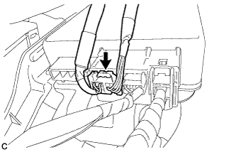
Connect the connector to the power steering ECU assembly.
-
Connect the connector to the power steering ECU assembly.
Tech Tips
As shown in the illustration, securely return the lock lever to its original position to connect the connector.
-
Engage the 2 wire harness clamps.
-
-
CONNECT NO. 2 STEERING INTERMEDIATE SHAFT ASSEMBLY
-
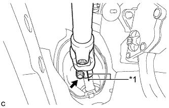
Text in Illustration *1 Matchmark Align the matchmarks on the No. 2 steering intermediate shaft assembly and steering intermediate shaft to connect the No. 2 steering intermediate shaft assembly to the steering intermediate shaft.
-
Install the bolt.
- Torque:
- 35 N*m { 357 kgf*cm, 26 ft.*lbf }
-
-
INSTALL COLUMN HOLE COVER SILENCER SHEET
-
Install the column hole cover silencer sheet with the 2 clips.
-
Install the floor carpet.
-
-
INSTALL NO. 2 AIR DUCT SUB-ASSEMBLY
-
Engage the 2 claws to install the No. 2 air duct sub-assembly.
-
-
INSTALL BRAKE PEDAL SUPPORT ASSEMBLY
for LHD: Click here
for RHD: Click here
-
INSTALL PUSH ROD PIN
for LHD: Click here
for RHD: Click here
-
INSTALL BRAKE PEDAL RETURN SPRING
for LHD: Click here
for RHD: Click here
-
INSTALL STOP LIGHT SWITCH MOUNTING ADJUSTER
-
INSTALL STOP LIGHT SWITCH ASSEMBLY
-
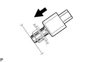
Insert the stop light switch assembly until the rod hits the pedal.
Note
When inserting the stop light switch assembly, support the pedal from behind so that the pedal is not pushed in.
-
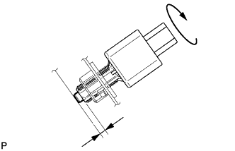
Make a quarter turn clockwise to install the stop light switch assembly.
- Torque:
- 1.5 N*m { 15 kgf*cm, 13 in.*lbf, or less }
Note
When inserting the stop light switch assembly, support the pedal from behind so that the pedal is not pushed in.
-
Connect the connector.
-
Check the protrusion of the rod.
Protrusion of the rod 1.5 to 2.5 mm (0.0591 to 0.0984 in.) If the protrusion is not as specified, adjust it.
Note
Do not depress the brake pedal.
-
-
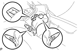
INSTALL DRIVER SIDE JUNCTION BLOCK ASSEMBLY (for LHD)
-
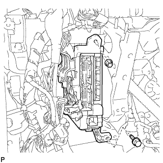
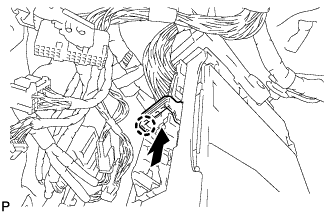
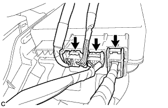
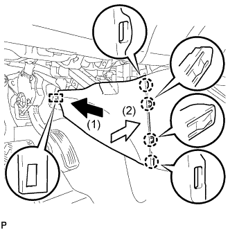
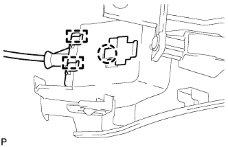
Engage the claw to install the connector as shown in the illustration.
Note
Be sure to engage each connector securely.
-
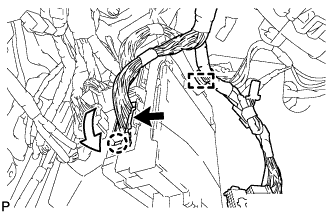
Engage the claw to lock the connector lock as shown in the illustration.
-
Engage the claw to connect the connector as shown in the illustration.
Note
Be sure to engage each connector securely.
-
Engage the 2 clamps to connect the wire harness.
-
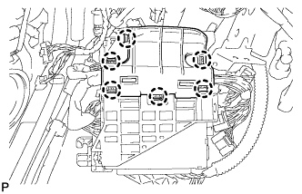
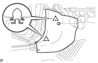
Engage the 6 claws to install the junction block cover.
-
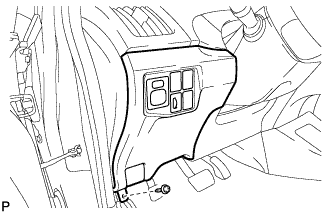
Install the driver side junction block assembly with the bolt and nut.
- Torque:
- 14 N*m { 138 kgf*cm, 10 ft.*lbf }
-
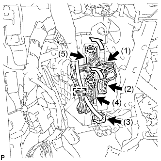
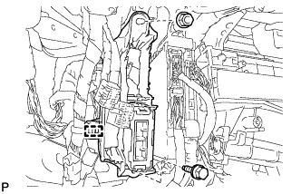
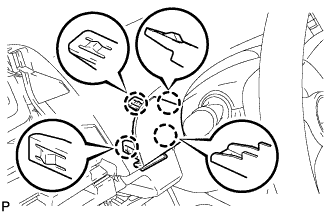
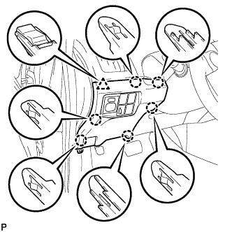
Engage the 2 claws to connect the 2 connectors (5) and (4) as shown in the illustration.
Note
Be sure to engage each connector securely.
-
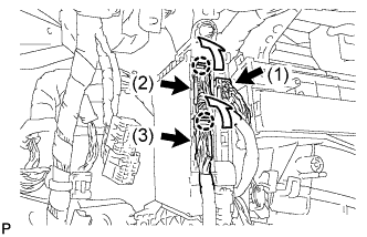
Connect the 3 connectors (3), (2) and (1) as shown in the illustration.
Note
Be sure to engage each connector securely.
-
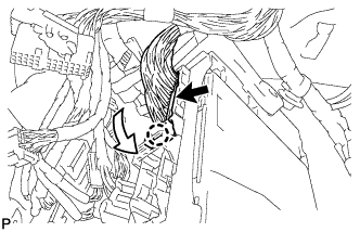
Engage the clamp to connect the wire harness.
-
-
INSTALL FRONT PASSENGER SIDE JUNCTION BLOCK ASSEMBLY (for RHD)
-
Engage the claw to connect the connector as shown in the illustration.
-
Engage the claw to lock the connector lock as shown in the illustration.
-
Engage the claw to connect the connector as shown in the illustration.
-
Engage the clamp to connect the wire harness.
-

Install the front passenger side junction block assembly with the bolt and nut.
- Torque:
- 14 N*m { 138 kgf*cm, 10 ft.*lbf }
-
Engage the 2 clamps to connect the wire harness.
-
Engage the 2 claws to connect the 2 connectors (3) and (2) as shown in the illustration.
-
Connect the connector (1).
-
-
INSTALL ECU INTEGRATION BOX LH (for RHD)
-
Install the ECU integration box with the bolt and nut.
- Torque:
- 14 N*m { 138 kgf*cm, 10 ft.*lbf }
-
Engage the clamp to connect the wire harness.
-
-
INSTALL HEADUP DISPLAY
-
Install the headup display with the bolt and 2 nuts.
-
Connect the connector.
-
Engage the clamp.
-
-
INSTALL LOWER INSTRUMENT PANEL SUB-ASSEMBLY (for LHD)
-
When using a new lower instrument panel sub-assembly:
-
Immediately before installing the lower instrument panel sub-assembly, twist and cut off the portions shown in the illustration.
-
-
Install the lower instrument panel sub-assembly with the 4 bolts <B>, 11 bolts <C> and screw <D>.
Text in Illustration *1 Bolt <B> *2 Bolt <C> *3 Screw <D> - - -
Engage each clamp.
-
-
INSTALL LOWER INSTRUMENT PANEL SUB-ASSEMBLY (for RHD)
-
When using a new lower instrument panel sub-assembly:
-
Immediately before installing the lower instrument panel sub-assembly, twist and cut off the portions shown in the illustration.
-
-
Install the lower instrument panel sub-assembly with the 4 bolts <B>, 11 bolts <C> and screw <D>.
Text in Illustration *1 Bolt <B> *2 Bolt <C> *3 Screw <D> - - -
Engage each clamp.
-
Engage the 2 claws.
-
-
INSTALL NO. 2 ANTENNA CORD SUB-ASSEMBLY (for LHD)
-
for Connector Type Antenna Cord:
-
Engage the 4 clamps.
-
Install the No. 2 antenna cord sub-assembly with the bolt.
-
Connect the connector.
-
-
for Plug Type Antenna Cord:
-
Engage the 5 clamps.
-
Install the No. 2 antenna cord sub-assembly with the bolt.
-
Connect the 2 connectors.
-
-
-
INSTALL NO. 2 ANTENNA CORD SUB-ASSEMBLY (for RHD)
-
for Connector Type Antenna Cord:
-
Engage the 5 clamps.
-
Install the No. 2 antenna cord sub-assembly with the bolt.
-
Connect the connector.
-
-
for Plug Type Antenna Cord:
-

Engage the 6 clamps.
-
Install the No. 2 antenna cord sub-assembly with the bolt.
-
Connect the 2 connectors.
-
-
-
INSTALL INSTRUMENT PANEL SAFETY PAD PLATE SUB-ASSEMBLY (for LHD)
-
Install the instrument panel safety pad plate sub-assembly with the 2 bolts <B>.
-
-
INSTALL POWER STEERING ECU ASSEMBLY
-
Install the power steering ECU assembly with the bolt and 2 nuts.
- Torque:
- 8.0 N*m { 82 kgf*cm, 71 in.*lbf }
-
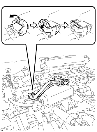
Connect the 3 connectors to the power steering ECU assembly.
-
Text in Illustration *1 Lock Lever *2 Lock of the Lock Lever Connect the connector to the power steering ECU assembly.
Tech Tips
As shown in the illustration, return the lock lever to its original position to connect the connector and securely push in the lock of the lock lever.
-
Engage the wire harness clamp to the power steering ECU assembly.
-
-
INSTALL COMBINATION METER ASSEMBLY
-
Engage the clip.
-
Install the combination meter assembly with the 3 screws.
-
Engage the clamp.
-
Connect the 3 connectors.
-
-
INSTALL NO. 1 HEATER TO REGISTER DUCT
-
Install the No. 1 heater to register duct with the 3 clips.
-
-
INSTALL COWL SIDE TRIM BOARD RH
Tech Tips
Use the same procedure for the RH side and LH side.
-
INSTALL FRONT DOOR SCUFF PLATE RH
Tech Tips
Use the same procedure for the RH side and LH side.
-
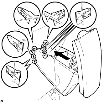
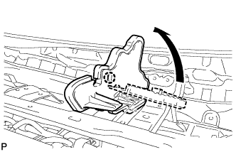
INSTALL GLOVE COMPARTMENT DOOR ASSEMBLY
-
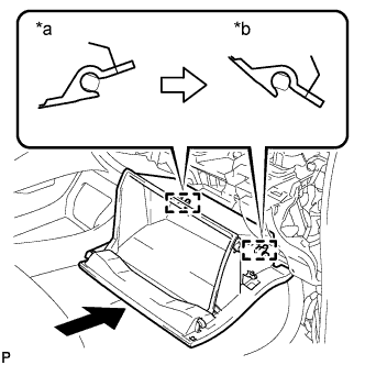
Text in Illustration *a Opened Approximately 55° *b Closed With the glove compartment door assembly opened approximately 55° from its closed position, engage the 2 hinges horizontally.
Note
Engaging the hinges from the top will deform the hinges. Be sure to install the glove compartment door assembly horizontally.
-
Text in Illustration *1 Glove Compartment Door Stopper Sub-assembly *2 Stopper Slightly bend the stoppers (A) and (B) in the directions indicated by the arrows in the illustration and engage the stoppers to install the glove compartment door assembly.
-
Engage the claw and connect the glove compartment door stopper sub-assembly.
-
-
INSTALL NO. 2 INSTRUMENT PANEL UNDER COVER SUB-ASSEMBLY
-
Connect the connector.
-
Engage the guide and 3 claws to install the No. 2 instrument panel under cover sub-assembly.
-
-
INSTALL DRIVER SIDE KNEE AIRBAG ASSEMBLY
-
Check that the power switch is off.
-
Check that the cable is disconnected from the negative (-) battery terminal.
CAUTION:
Wait at least 90 seconds after disconnecting the cable from the negative (-) battery terminal to disable the SRS system.
-
Connect the airbag connector and install the clamp to the driver side knee airbag assembly.
Note
When connecting any airbag connector, take care not to damage the airbag wire harness.
-
Push in the lock to install the airbag connector.
-
Temporarily install the driver side knee airbag assembly with the 6 claws and 4 guides.
-
Install the driver side knee airbag assembly with the 4 bolts.
- Torque:
- 10 N*m { 102 kgf*cm, 7 ft.*lbf }
Note
Confirm that the driver side knee airbag assembly is installed securely without any excessive gaps and is not protruding outward.
-
-
INSTALL NO. 1 INSTRUMENT PANEL UNDER COVER SUB-ASSEMBLY (for LHD)
-
Connect each connector.
-
Engage the guide and claw.
-
Install the No. 1 instrument panel under cover sub-assembly with the 2 screws <D>.
-
-
INSTALL NO. 1 INSTRUMENT PANEL UNDER COVER SUB-ASSEMBLY (for RHD)
-
Connect each connector.
-
Engage the guide and 2 claws.
-
Install the No. 1 instrument panel under cover sub-assembly with the screw <D>.
-
-
ALIGN FRONT WHEELS FACING STRAIGHT AHEAD
-
INSTALL TURN SIGNAL SWITCH ASSEMBLY WITH SPIRAL CABLE SUB-ASSEMBLY
-
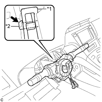
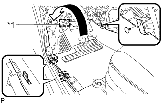
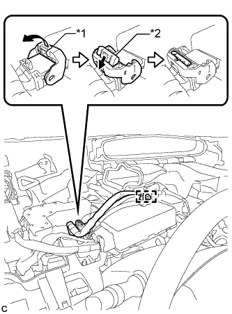
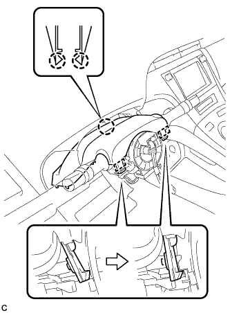
Text in Illustration *1 Clamp *2 Claw Using pliers, expand the clamp.
-
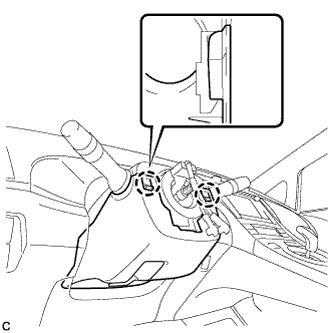
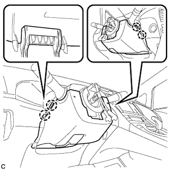
While holding the clamp expanded, install the turn signal switch assembly with spiral cable sub-assembly to the steering column assembly and engage the claw.
-
Return the clamp to its original position.
-
Connect the connectors to the turn signal switch assembly with spiral cable sub-assembly.
-
-
INSTALL UPPER STEERING COLUMN COVER
-
Engage the 2 claws and 2 pins to install the upper steering column cover.
-
-
INSTALL LOWER STEERING COLUMN COVER
Note
If the lower steering column cover is installed in the incorrect order, it will not be possible to assemble the lower steering column cover.
-
Engage the 2 claws to install the lower steering column cover.
-
Engage the 4 claws.
-
Engage the 2 claws.
Tech Tips
Press the area around the claws to engage them.
-
-
INSTALL STEERING WHEEL ASSEMBLY
-
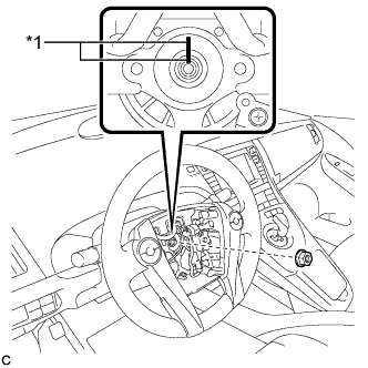
Text in Illustration *1 Matchmark Align the matchmarks on the steering wheel assembly and steering main shaft.
-
Install the steering wheel assembly set nut.
- Torque:
- 50 N*m { 510 kgf*cm, 37 ft.*lbf }
-
Connect the connectors to the spiral cable sub-assembly.
-
-
INSTALL STEERING PAD
-
Check that the power switch is off.
-
Check that the cable is disconnected from the negative (-) battery terminal.
CAUTION:
Wait at least 90 seconds after disconnecting the cable from the negative (-) battery terminal to disable the SRS system.
-

Connect the airbag connector to the steering pad.
Note
When connecting any airbag connector, take care not to damage the airbag wire harness.
-
Push in the lock to install the airbag connector.
-
Connect the horn connector to the steering pad.
-

Push the steering pad to engage the 2 pins.
Note
Make sure that the pins are securely inserted into the steering holes.
-
-
INSTALL LOWER NO. 3 STEERING WHEEL COVER
-

Engage the claw to install the lower No. 3 steering wheel cover.
-
-
INSTALL LOWER NO. 2 STEERING WHEEL COVER
-

Engage the claw to install the lower No. 2 steering wheel cover.
-
-
INSTALL NO. 1 SWITCH HOLE BASE
-
Connect the connector.
-
Engage the 5 claws to install the No. 1 switch hole base.
-
-
INSTALL UPPER INSTRUMENT PANEL FINISH PANEL ASSEMBLY
-
Temporarily install the console box assembly.
-
Engage the 9 claws as shown in the illustration.
-
Install the to install the upper instrument panel finish panel assembly with the 2 bolts <A>.
-
Engage the clamp.
-
-
INSTALL SHIFT LOCK CONTROL UNIT ASSEMBLY
-
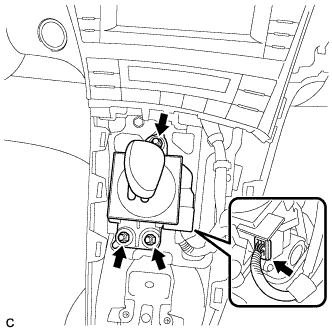
Install the shift lock control unit assembly with the 3 nuts.
- Torque:
- 12 N*m { 122 kgf*cm, 9 ft.*lbf }
-
Connect the connector to the shift lock control unit assembly.
-
-
INSTALL AIR CONDITIONING CONTROL ASSEMBLY
-
Connect the connector.
Note
Since the connectors for the air conditioning control assembly and the integration control and panel sub-assembly are the same shape, take care to connect each connector to the correct component.
-
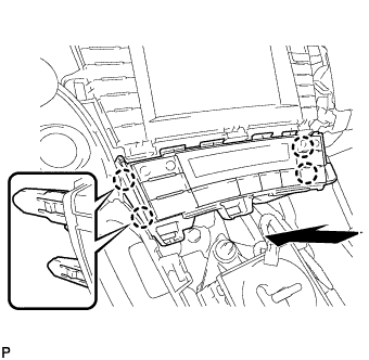
Engage the 4 claws to install the air conditioning control assembly.
-
-
INSTALL CONSOLE BOX ASSEMBLY
-
Connect each connector.
-
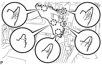
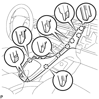
Engage the 4 guides and 2 claws as shown in the illustration.
-
Install the console box assembly with the bolt <B> and 2 clips.
-
-
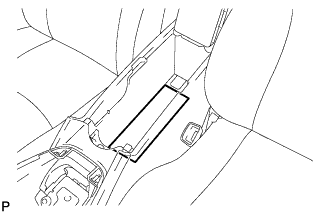
INSTALL BOX BOTTOM MAT
-
Engage the fastener to install the box bottom mat.
-
-
INSTALL FRONT NO. 2 CONSOLE BOX INSERT
-
Engage the guide and 4 claws to install the front No. 2 console box insert as shown in the illustration.
-
-
INSTALL FRONT NO. 1 CONSOLE BOX INSERT
-
Engage the guide and 4 claws to install the front No. 1 console box insert as shown in the illustration.
-
-
INSTALL NO. 2 CONSOLE BOX MOUNTING BRACKET
-
Install the No. 2 console box mounting bracket with the 6 bolts <B>.
-
-
INSTALL ELECTRICAL KEY OSCILLATOR
-
Engage the clamp and install the electrical key oscillator.
Note
Be careful when installing the electrical key oscillator. If the oscillator is dropped, replace it with a new one.
-
Connect the connector.
-
-
INSTALL REAR CONSOLE BOX ASSEMBLY
-
Connect the connector.
-
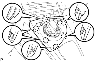
Engage the 8 claws as shown in the illustration.
-
Install the rear console box assembly with the 5 bolts.
-
-
INSTALL CONSOLE BOX CARPET
-
Install the console box carpet.
-
-
INSTALL UPPER CONSOLE PANEL
-
Engage the 3 claws to install the upper console panel.
-
-
INSTALL REAR CONSOLE BOX POCKET
-
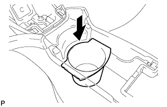
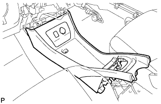
Install the rear console box pocket as shown in the illustration.
-
-
INSTALL UPPER INSTRUMENT PANEL ASSEMBLY
-
When using a new upper instrument panel sub-assembly:
-
Immediately before installing the upper instrument panel assembly, twist and cut off the portions shown in the illustration.
-
-
Engage the 5 claws as shown in the illustration.
-
Engage the 2 claws and 4 clips, and install the upper instrument panel assembly as shown in the illustration.
-
Install the 2 bolts <B>.
-
Install the 2 passenger airbag bolts <A>.
- Torque:
- 20 N*m { 204 kgf*cm, 15 ft.*lbf }
Text in Illustration *1 Passenger Airbag Bolt <A> *2 Bolt <B> -
Engage the 2 clamps.
-
Connect each connector.
-
-
CONNECT NO. 3 INSTRUMENT PANEL WIRE
-
Check that the power switch is off.
-
Check that the cable is disconnected from the negative (-) battery terminal.
CAUTION:
Wait at least 90 seconds after disconnecting the cable from the negative (-) battery terminal to disable the SRS system.
-
Connect the connector.
Note
When connecting any airbag connector, take care not to damage the airbag wire harness.
-
-
INSTALL CENTER INSTRUMENT CLUSTER FINISH PANEL GARNISH
-
Connect the connector.
-
Engage the 7 claws.
-
Install the center instrument cluster finish panel garnish with the 2 screws <C>.
-
-
INSTALL INSTRUMENT CLUSTER FINISH PANEL END
-
Engage the 2 guides and 5 claws to install the instrument cluster finish panel end as shown in the illustration.
-
-
INSTALL FRONT NO. 2 SPEAKER ASSEMBLY
Tech Tips
Use the same procedure for the RH side and LH side.
-
INSTALL NO. 2 INSTRUMENT PANEL SPEAKER PANEL SUB-ASSEMBLY
-
Engage the 2 guides and 6 claws to install the No. 2 instrument panel speaker panel sub-assembly as shown in the illustration.
-
-
INSTALL FRONT PILLAR GARNISH CORNER PIECE RH
-
Engage the 3 claws to install the front pillar garnish corner piece RH.
-
-
INSTALL FRONT PILLAR GARNISH RH
Tech Tips
Use the same procedure for the RH side and LH side.
-
INSTALL FRONT NO. 2 SPEAKER ASSEMBLY
-
Connect the connector.
-
Install the front No. 2 speaker assembly with the 2 bolts.
-
-
INSTALL NO. 1 INSTRUMENT PANEL SPEAKER PANEL SUB-ASSEMBLY
-
Engage the 2 guides and 6 claws to install the No. 1 instrument panel speaker panel sub-assembly as shown in the illustration.
-
-
INSTALL FRONT PILLAR GARNISH CORNER PIECE LH
-
Engage the 3 claws to install the front pillar garnish corner piece LH.
-
-
INSTALL FRONT PILLAR GARNISH LH
-
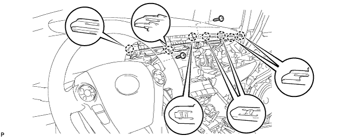
Text in Illustration *1 Adhesive Tape *2 Protective Cover *3 Curtain Shield Airbag Assembly Remove the protective cover.
-
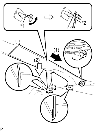
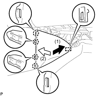
Text in Illustration *1 Front Pillar Garnish Clip *2 Protective Tape Make sure that the front pillar garnish clip is not damaged.
Note
-
If there is any damage, replace the garnish clip with a new one.
-
When a garnish clip is being replaced, make sure to install it in the direction shown in the illustration.
-
-
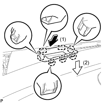
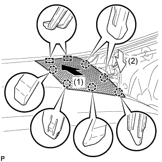
Engage the claw to direction indicated by the arrow (1).
-
Engage the 3 guides to direction indicated by the arrow (2).
-
Turn the end of the front pillar garnish clip 90° with needle-nosed pliers and install it to the front pillar garnish LH.
Tech Tips
Tape the needle-nosed pliers tip before use.
-
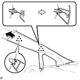
Engage 2 clips to install the front pillar garnish LH.
-
-
INSTALL INSTRUMENT PANEL FINISH PANEL END RH
-
Engage the guide as shown in the illustration.
-
Engage the guide as shown in the illustration.
-
Engage the 4 claws to install the instrument panel finish panel end RH.
-
-
CONNECT FRONT DOOR OPENING TRIM WEATHERSTRIP RH
-
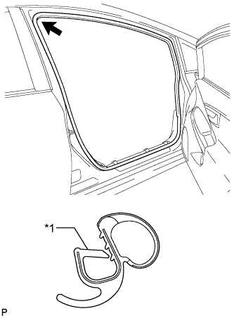
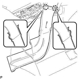
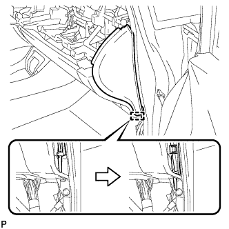
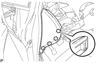
Text in Illustration *1 Alignment Mark (White) Align the alignment mark (White) on the weatherstrip with the protruding portion on the body indicated by the arrow in the illustration, and install the front door opening trim weatherstrip RH.
Note
After installation, check that the corners fit correctly.
-
-
INSTALL GLOVE COMPARTMENT DOOR
-
Open the glove compartment door assembly.
-
Insert the glove compartment door as shown in the illustration.
-
Engage the 7 claws to install the glove compartment door.
-
-
INSTALL NO. 2 INSTRUMENT PANEL REGISTER
-
Engage the 3 claws and clip to install the No. 2 instrument panel register.
-
-
INSTALL NO. 1 SIDE DEFROSTER NOZZLE
-
Engage the 3 claws to install the No. 1 side defroster nozzle.
-
-
INSTALL INSTRUMENT PANEL FINISH PANEL END LH
-
Engage the guide as shown in the illustration.
-
Engage the guide as shown in the illustration.
-
Engage the 4 claws to install the instrument panel finish panel end LH.
-
-
CONNECT FRONT DOOR OPENING TRIM WEATHERSTRIP LH
-
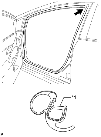
Text in Illustration *1 Alignment Mark (Yellow) Align the alignment mark (Yellow) on the weatherstrip with the protruding portion on the body indicated by the arrow in the illustration, and install the front door opening trim weatherstrip LH.
Note
After installation, check that the corners fit correctly.
-
-
INSTALL NO. 1 CENTER INSTRUMENT CLUSTER FINISH PANEL
-
Engage the 4 claws to install the No. 1 center instrument cluster finish panel.
-
-
INSTALL NO. 1 INSTRUMENT PANEL REGISTER
-
Engage the 4 claws to install the No. 1 instrument panel register.
-
-
INSTALL LOWER INSTRUMENT PANEL FINISH PANEL ASSEMBLY
-
Connect each connector.
-
Engage the clamp.
-
Engage the 2 guides and claw to connect the hood lock control cable.
-
Engage the 6 claws and clip.
-
Install the lower instrument panel finish panel assembly with the screw <C>.
-
-
INSTALL COWL SIDE TRIM SUB-ASSEMBLY LH
-
Engage the 2 clips.
-
Install the cowl side trim board LH with the clip.
-
-
INSTALL FRONT DOOR SCUFF PLATE LH
-
Engage the 10 claws to install the front door scuff plate LH.
-
-
INSTALL NAVIGATION RECEIVER WITH BRACKET (w/ Navigation System)
-
Engage the 4 claws to temporarily install the navigation receiver assembly with bracket as shown in the illustration.
-
Install the navigation receiver assembly with bracket with the 4 bolts.
-
-
INSTALL RADIO RECEIVER WITH BRACKET (w/o Navigation System)
-
Connect each connector.
-
Engage the 4 claws as shown in the illustration.
-
Install the radio receiver with bracket with the 4 bolts.
-
-
INSTALL RADIO TUNER OPENING COVER WITH BRACKET (w/o Radio Receiver)
-
Install the radio tuner opening cover with bracket with the 4 bolts <B>.
-
-
INSTALL CENTER INSTRUMENT CLUSTER FINISH PANEL SUB-ASSEMBLY (w/o Radio Receiver)
-
Engage the 4 claws to install the center instrument cluster finish panel sub-assembly.
-
-
INSTALL UPPER INSTRUMENT PANEL FINISH PANEL SUB-ASSEMBLY
-
Connect the connector.
-
Engage the 3 claws to install the upper instrument panel finish panel sub-assembly.
-
-
INSTALL INSTRUMENT CLUSTER FINISH PANEL GARNISH
-
Connect the connector.
-
Engage the 14 claws to install the instrument cluster finish panel garnish.
-
-
INSTALL LOWER CENTER INSTRUMENT CLUSTER FINISH PANEL SUB-ASSEMBLY
-
Engage the 7 claws and 2 clips to install the lower center instrument cluster finish panel sub-assembly.
-
-
INSTALL INTEGRATION CONTROL AND PANEL ASSEMBLY
-
Connect each connector.
-
Engage the 6 claws to install the integration control and panel assembly.
-
-
CONNECT OUTLET HEATER WATER HOSE
-
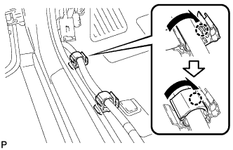
Using pliers, grip the claws of the clip and slide the clip to connect the outlet heater water hose.
-
-
CONNECT INLET HEATER WATER HOSE
-
Using pliers, grip the claws of the clip and slide the clip to connect the inlet heater water hose.
-
-
CONNECT AIR CONDITIONING TUBE AND ACCESSORY ASSEMBLY
-
Remove the attached vinyl tape from the pipe.
-
Sufficiently apply compressor oil to a new O-ring and the fitting surface of the air conditioning tube and accessory assembly.
Compressor oil ND-OIL 11 or equivalent -
Install the O-ring on the air conditioning tube and accessory assembly.
Note
-
Keep the O-ring and O-ring fitting surfaces clean from dirt or any foreign objects.
-
Do not use any compressor oil other than ND-OIL 11 or equivalent. If any compressor oil other than ND-OIL 11 or equivalent is used, compressor motor insulation performance may decrease, resulting in a leakage of electric power.
-
-
Install the air conditioning tube and accessory assembly.
-
-
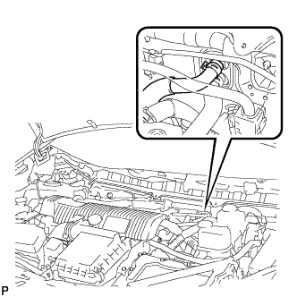
CONNECT SUCTION PIPE SUB-ASSEMBLY
-
Remove the attached vinyl tape from the pipe.
-
Sufficiently apply compressor oil to a new O-ring and the fitting surface of the suction pipe sub-assembly.
Compressor oil ND-OIL 11 or equivalent -
Install the O-ring on the suction pipe sub-assembly.
Note
-
Keep the O-ring and O-ring fitting surfaces clean from dirt or any foreign objects.
-
Do not use any compressor oil other than ND-OIL 11 or equivalent. If any compressor oil other than ND-OIL 11 or equivalent is used, compressor motor insulation performance may decrease, resulting in a leakage of electric power.
-
-
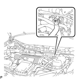
Install the suction pipe sub-assembly.
-
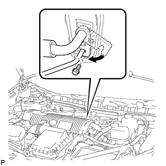
Move the hook connector in the direction indicated by the arrow in the illustration.
-
Insert the pipe joint into the fitting hole securely and tighten the bolt.
- Torque:
- 9.8 N*m { 100 kgf*cm, 87 in.*lbf }
-
-
INSTALL OUTER COWL TOP PANEL SUB-ASSEMBLY (for LHD)
-
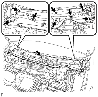
Install the outer cowl top panel sub-assembly with the 9 bolts.
- Torque:
- 12 N*m { 122 kgf*cm, 9 ft.*lbf }
-
Bend the water guard plate RH and engage the claw.
-
Bend the No. 1 heater air duct splash shield seal and engage the claw.
-
Engage the clamp to install the wire harness.
-
-
INSTALL OUTER COWL TOP PANEL SUB-ASSEMBLY (for RHD)
-
Install the outer cowl top panel with the 9 bolts.
- Torque:
- 12 N*m { 122 kgf*cm, 9 ft.*lbf }
-
Bend the water guard plate RH and engage the claw.
-
Bend the No. 1 heater air duct splash shield seal and engage the claw.
-
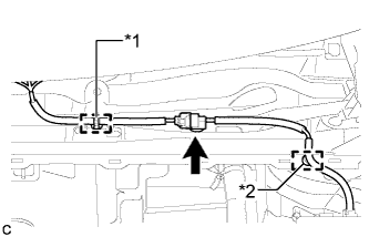
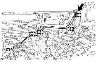
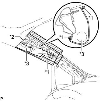
Engage the clamp*2 of the wire harness.
-
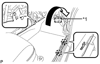
Engage the clamp*1 and connect the connector (w/ Windshield Deicer).
-
Engage the clamp of the wire harness.
-
-
INSTALL COWL BODY MOUNTING REINFORCEMENT LH (for LHD)
-
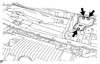
Install the cowl body mounting reinforcement LH with the 3 bolts.
- Torque:
- 12 N*m { 122 kgf*cm, 9 ft.*lbf }
-
-
INSTALL COWL BODY MOUNTING REINFORCEMENT LH (for RHD)
-
Install the cowl body mounting reinforcement LH with the 3 bolts.
- Torque:
- 12 N*m { 122 kgf*cm, 9 ft.*lbf }
-
-
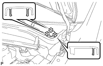
INSTALL WINDSHIELD WIPER MOTOR AND LINK ASSEMBLY
-
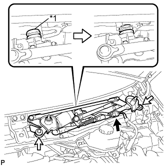
Text in Illustration *1 Grommet Engage the grommet as shown in the illustration.
Note
Be careful not to damage the windshield when installing the windshield wiper motor and link assembly.
-
Install the windshield wiper motor and link assembly with the 2 bolts.
- Torque:
- 5.5 N*m { 56 kgf*cm, 49 in.*lbf }
-
Connect the connector.
-
-
INSTALL COWL TOP VENTILATOR LOUVER SUB-ASSEMBLY (for LHD)
-
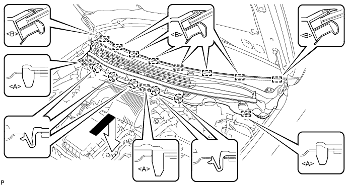
Engage the 8 guides <B>.
-
Engage the 5 claws and 3 guides <A> to install the cowl top ventilator louver sub-assembly as shown in the illustration.
-
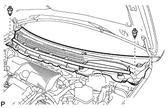
Install the 2 clips.
-
-
INSTALL COWL TOP VENTILATOR LOUVER SUB-ASSEMBLY (for RHD)
-
Engage the 8 guides <B>.
-
Engage the 6 claws and 3 guides <A> to install the cowl top ventilator louver sub-assembly as shown in the illustration.
-
Install the 2 clips.
-
-
INSTALL COWL SIDE VENTILATOR SUB-ASSEMBLY LH
-
Engage the guide <B> as shown in the illustration.
-
Engage the claw and guide <A> to install the cowl side ventilator sub-assembly LH as shown in the illustration.
-
-
INSTALL COWL SIDE VENTILATOR SUB-ASSEMBLY RH
Tech Tips
Use the same procedure for the RH side and LH side.
-
INSTALL FRONT WIPER ARM AND BLADE ASSEMBLY RH
-
Operate the wiper and stop the windshield wiper motor at the automatic stop position.
-
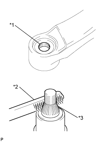
Text in Illustration *1 Wiper Arm Serration *2 Wire Brush *3 Wiper Pivot Serration When reusing the front wiper arm and blade assembly RH:
-
Clean the wiper arm serrations.
-
-
When reusing the windshield wiper link assembly:
-
Clean the wiper pivot serrations with a wire brush.
-
-
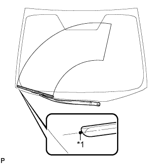
Text in Illustration *1 Ceramic Dot Install the front wiper arm and blade assembly RH with the nut to the position shown in the illustration.
- Torque:
- 23 N*m { 235 kgf*cm, 17 ft.*lbf }
Tech Tips
Hold the wiper arm by hand while tightening the nut.
-
-
INSTALL FRONT WIPER ARM AND BLADE ASSEMBLY LH
-

Text in Illustration *1 Wiper Arm Serration *2 Wire Brush *3 Wiper Pivot Serration When reusing the front wiper arm and blade assembly LH:
-
Clean the wiper arm serrations.
-
-
When reusing the windshield wiper link assembly:
-
Clean the wiper pivot serrations with a wire brush.
-
-
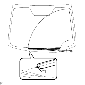
Text in Illustration *1 Ceramic Dot Install the front wiper arm and blade assembly LH with the nut to the position shown in the illustration.
- Torque:
- 23 N*m { 235 kgf*cm, 17 ft.*lbf }
Tech Tips
Hold the wiper arm by hand while tightening the nut.
-
Operate the front wipers while spraying washer fluid on the windshield glass. Make sure that the front wipers function properly and there is no interference with the vehicle body.
-
-
INSTALL FRONT WIPER ARM HEAD CAP
-
Engage the 3 claws to install the front wiper arm head cap.
Tech Tips
Use the same procedure for the RH side and LH side.
-
-
CONNECT CABLE TO NEGATIVE BATTERY TERMINAL
Note
When disconnecting the cable, some systems need to be initialized after the cable is reconnected Click here.
-
INSTALL REAR NO. 3 FLOOR BOARD
-

Engage the 2 guides to install the rear No. 3 floor board.
-
-
INSTALL REAR DECK FLOOR BOX
-
Install the rear deck floor box.
-
-
INSTALL REAR NO. 2 FLOOR BOARD
-

Engage the 3 guides <A>.
-
Engage the 2 guides <B> and install the rear No. 2 floor board as shown in the illustration.
-
-
ADD COOLANT (for Engine)
-
Tighten the radiator drain cock plug.
-
Tighten the cylinder block drain cock plug.
- Torque:
- 13 N*m { 130 kgf*cm, 9 ft.*lbf }
-
Remove the reservoir tank cap.
-
Connect the hose to the air release valve.
-
Loosen the air release valve.
-
Add TOYOTA Super Long Life Coolant (SLLC) to the reservoir tank filler opening until coolant overflows from the air release valve. Then tighten the air release valve.
Standard Capacity Item Capacity Engine coolant w/ Exhaust Heat Recirculation System:
7.2 liters (7.6 US qts, 6.3 lmp. qts)
w/o Exhaust Heat Recirculation System:
6.5 liters (6.8 US qts, 5.7 lmp. qts)
Tech Tips
-
TOYOTA vehicles are filled with TOYOTA SLLC at the factory. In order to avoid damage to the engine cooling system and other technical problems, only use TOYOTA SLLC or similar high quality ethylene glycol based non-silicate, non-amine, non-nitrite, non-borate coolant with long-life hybrid organic acid technology (coolant with long-life hybrid organic acid technology is a combination of low phosphates and organic acids).
-
Contact your TOYOTA dealer for further details.
Note
Never use water as a substitute for engine coolant.
-
-
Disconnect the hose from the air release valve.
-
Text in Illustration *1 B Line Add coolant to B line of the reservoir tank.
-
Squeeze the inlet and outlet radiator hoses several times by hand, and then check the level of the coolant.
If the coolant level is low, add coolant.
-
Put the engine in inspection mode Click here.
-
Install the reservoir tank cap and air release valve, and warm up the engine sufficiently.
-
Bleed air from the cooling system.
Note
-
Before starting the engine, turn the A/C switch off.
-
Adjust the heater control to the maximum hot setting.
-
Adjust the blower speed to low setting.
-
Warm up the engine until the thermostat opens. While the thermostat is open, allow the coolant to circulate for several minutes.
Tech Tips
The thermostat opening timing can be confirmed by squeezing the inlet radiator hose by hand, and sensing vibrations when the engine coolant starts to flow inside the hose.
CAUTION:
When squeezing the radiator hose:
-
Wear protective gloves.
-
Be careful as the radiator hoses are hot.
-
Keep your hands away from the radiator fan.
-
-
Squeeze the inlet and outlet radiator hoses several times by hand to bleed air from the system.
CAUTION:
When squeezing the radiator hose:
-
Wear protective gloves.
-
Be careful as the radiator hoses are hot.
-
Keep your hands away from the radiator fan.
-
-
-
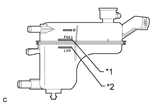
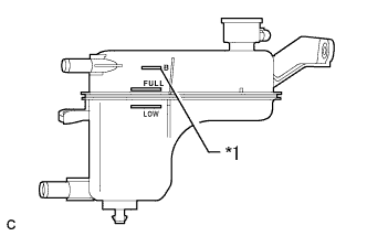
Text in Illustration *1 Full Line *2 Low Line After the engine has cooled down, check that the coolant level is between full and low.
If the coolant level is low, add coolant to the full line on the reservoir tank.
-
-
CHARGE WITH REFRIGERANT
-
Perform vacuum purging using a vacuum pump.
-
Charge with refrigerant HFC-134a (R134a).
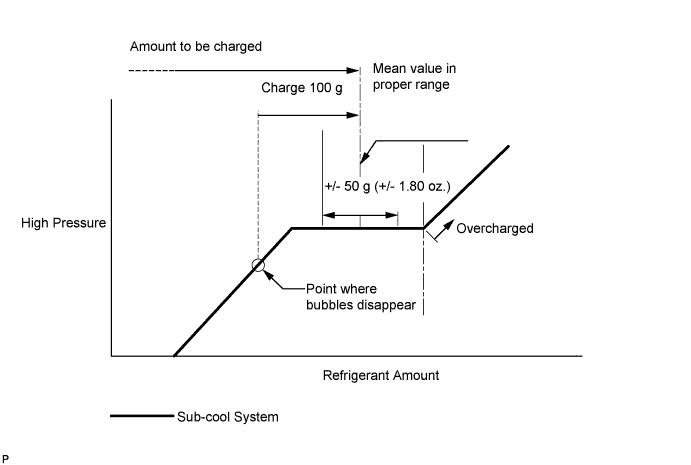
Standard 470 g (16.6 oz.) - SST
- 09985-20010 ( 09985-02010, 09985-02050, 09985-02060, 09985-02070, 09985-02080, 09985-02090, 09985-02110, 09985-02130, 09985-02140, 09985-02150 )
Note
-
Do not turn the A/C on before charging with refrigerant. Doing so will cause the compressor to work without refrigerant, resulting in overheating of the cooler compressor.
-
Approximately 100 g (3.53 oz.) of refrigerant may need to be charged after bubbles disappear. The refrigerant amount should be checked by quantity, not with the sight glass.
-
Avoid using the gauge manifold set that had been used for vehicles with conventional compressor oil (ND-OIL 8 or equivalent) as much as possible. This will cause compressor oil remaining in the manifold to enter the vehicle, resulting in insulation performance deterioration. A gauge manifold set that had been used 3 times or less can be reused if an appropriate one is not available.
Tech Tips
Ensure that sufficient refrigerant is available to recharge the system when using a refrigerant recovery unit. Refrigerant recovery units are not always able to recover 100% of the refrigerant from an A/C system.
-
-
WARM UP COMPRESSOR
-
Keep the A/C switch on for at least 2 minutes to warm up the compressor.
Note
Be sure to warm up the compressor when turning the A/C on after removing and installing the cooler refrigerant lines (including the compressor), to prevent damage to the compressor.
-
-
INSPECT FOR REFRIGERANT LEAK
-
After recharging with refrigerant, inspect for refrigerant leaks using a halogen leak detector.
-
Carry out the test under the following conditions:
-
Turn the power switch off.
-
Secure good ventilation (the halogen leak detector may react to volatile gases which are not refrigerant, such as evaporated gasoline and exhaust gas).
-
Repeat the test 2 or 3 times.
-
Make sure that there is some refrigerant remaining in the refrigeration system.
When the compressor is off: approx. 392 to 588 kPa (3.9 to 5.9 kgf/cm2, 57 to 85 psi)
-
-
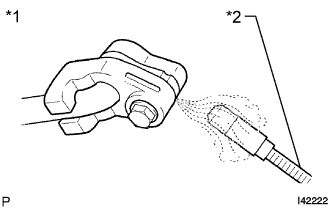
Text in Illustration *1 Inspect for Leak *2 Halogen Leak Detector Using a halogen leak detector, inspect for refrigerant leaks from the refrigerant lines.
-
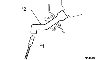
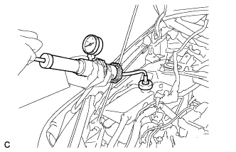
Text in Illustration *1 Halogen Leak Detector *2 Drain Hose Bring the halogen leak detector close to the drain hose with the detector's power off, and then turn the detector on.
Tech Tips
-
After the blower motor has stopped, let the cooling unit stand for more than 15 minutes.
-
Bring the halogen leak detector sensor under the drain hose.
-
When bringing the halogen leak detector close to the drain hose, make sure that the halogen leak detector does not react to volatile gases. If it is not possible to avoid interference from volatile gases, the vehicle should be lifted up to allow testing.
-
-
If a refrigerant leak is not detected from the drain hose, remove the blower motor control from the cooling unit. Insert the halogen leak detector sensor into the unit and perform the test.
-
Disconnect the pressure switch connector and leave it for approximately 20 minutes. Bring the halogen leak detector close to the pressure switch and perform the test.
-
-
INSPECT FOR COOLANT LEAK (for Engine)
CAUTION:
Do not remove the reservoir tank cap while the engine and radiator are still hot. Pressurized, hot engine coolant and steam may be released and cause serious burns.
Note
Before performing each inspection, turn the A/C switch off.
-
Remove the reservoir tank cap.
-
Fill the radiator and reservoir with coolant, and then attach a radiator cap tester.
-
Put the engine in inspection mode Click here.
-
Warm up the engine.
-
Using the reservoir cap tester, increase the pressure inside the radiator to 108 kPa (1.1 kgf/cm2, 16 psi), and check that the pressure does not drop. If the pressure drops, check the hoses, radiator, front exhaust pipe assembly and the heater hose around and engine water pump assembly for leaks. If no external leaks are found, check the heater core, cylinder block and cylinder head.
-
Remove the radiator cap tester.
-
Install the reservoir tank cap.
-
-
INSPECT SHIFT LEVER
-
Turn the power switch on (READY).
-
Check that all available shift positions can be selected moving the shift lever.
Tech Tips
After the shift lever is replaced with a new one, perform the above operation. If this operation is not performed, moving the shift lever may not initially select shift positions.
-
-
INSPECT STEERING PAD
-
Inspect the steering pad Click here.
-
-
INSPECT SRS WARNING LIGHT
-
Inspect the SRS warning light Click here.
-