CONDENSER REMOVAL

-
PRECAUTION (w/ Navigation System for HDD)
Note
After the power switch is turned off, the display and navigation module display (HDD navigation system) records various types of memory and settings. As a result, after turning the power switch off, make sure to wait at least 60 seconds before disconnecting the cable from the negative (-) battery terminal.
-
RECOVER REFRIGERANT FROM REFRIGERATION SYSTEM
-
Turn the A/C switch on.
-
Operate the A/C with the setting temperature at 25°C (77°F) and the blower level at LO for 10 minutes to circulate the refrigerant. This causes most of the compressor oil from the various components of the A/C system to collect in the A/C compressor.
-
Turn the power switch off.
-
Recover the refrigerant from the A/C system using a refrigerant recovery unit.
-
-
REMOVE REAR NO. 2 FLOOR BOARD
-

Disengage the 2 guides <A> as shown in the illustration.
-
Disengage the 3 guides <B> and remove the rear No. 2 floor board.
-
-
REMOVE REAR DECK FLOOR BOX
-
Remove the rear deck floor box.
-
-
REMOVE REAR NO. 3 FLOOR BOARD
-

Disengage the 2 guides and remove the rear No. 3 floor board.
-
-
DISCONNECT CABLE FROM NEGATIVE BATTERY TERMINAL
Note
When disconnecting the cable, some systems need to be initialized after the cable is reconnected Click here.
-
REMOVE RADIATOR SUPPORT OPENING COVER
-
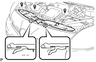
Remove the 3 clips.
-
Disengage the 2 claws and remove the radiator support opening cover.
-
-
REMOVE FRONT BUMPER ASSEMBLY
-
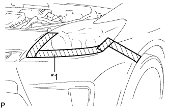
Text in Illustration *1 Protective Tape Put protective tape around the front bumper assembly.
Tech Tips
Use the same procedure for the RH side and LH side.
-
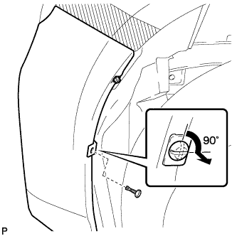
Using a screwdriver, turn the pin 90 degrees and remove the pin hold clip.
Tech Tips
Use the same procedure for the RH side and LH side.
-
Remove the screw.
Tech Tips
Use the same procedure for the RH side and LH side.
-
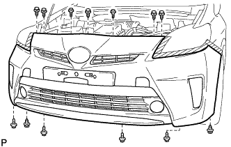
Remove the 2 bolts and 4 screws.
-
Using a clip remover, remove the 7 clips.
-
w/ Front Spoiler:
-
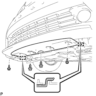
Using a clip remover, remove the 2 clips.
-
Remove the 2 screws.
-
Disengage the 2 guides and remove the front spoiler cover.
-
-
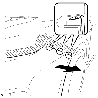
Disengage the 3 claws and remove the front bumper assembly.
Tech Tips
Use the same procedure for the RH side and LH side.
-
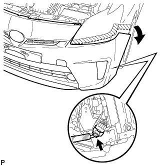
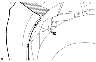
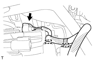
Pull back the side of the front bumper assembly as shown in the illustration and disconnect the connector.
Note
Do not apply excessive force when separating the front bumper.
-
w/ Headlight Cleaner System:
-
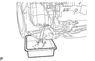
Disconnect the headlight cleaner hose and drain the washer fluid.
Tech Tips
Use a container to collect the washer fluid.
-
-
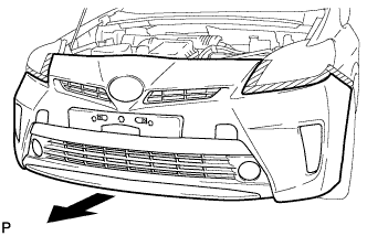
Remove the front bumper assembly as shown in the illustration.
-
-
REMOVE MILLIMETER WAVE RADAR SENSOR ASSEMBLY (w/ Dynamic Radar Cruise Control System)
-
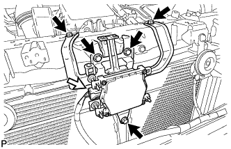
Disconnect the connector.
-
Remove the 5 bolts and millimeter wave radar sensor assembly.
-
-
REMOVE MILLIMETER WAVE RADAR SENSOR BRACKET (w/ Dynamic Radar Cruise Control System)
-
Remove the bolt and millimeter wave radar sensor bracket.
-
-
DISCONNECT DISCHARGE HOSE SUB-ASSEMBLY
-
Remove the bolt and disconnect the discharge hose sub-assembly.
-
Remove the O-ring from the discharge hose sub-assembly.
Note
Seal the openings of the disconnected parts using vinyl tape to prevent entry of moisture and foreign matter.
-
-
DISCONNECT AIR CONDITIONING TUBE AND ACCESSORY ASSEMBLY
-
Remove the bolt and disconnect the air conditioning tube and accessory assembly.
-
Remove the O-ring from the air conditioning tube and accessory assembly.
Note
Seal the openings of the disconnected parts using vinyl tape to prevent entry of moisture and foreign matter.
-
-
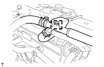
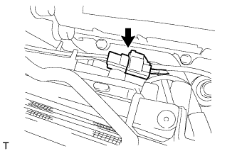
DISCONNECT NO. 5 INVERTER COOLING HOSE
-
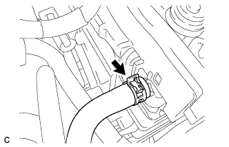
Using pliers, grip the claws of the clip and slide the clip to disconnect the No. 5 inverter cooling hose.
Note
-
Do not apply excessive force to the No. 5 inverter cooling hose.
-
Prepare a drain pan or cloth in case the coolant leaks.
-
-
-
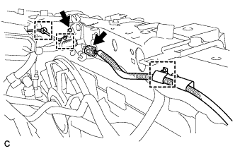
DISCONNECT NO. 7 INVERTER COOLING HOSE
-
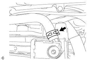
Using pliers, grip the claws of the clip and slide the clip to disconnect the No. 7 inverter cooling hose.
Note
-
Do not apply excessive force to the No. 7 inverter cooling hose.
-
Prepare a drain pan or cloth in case the coolant leaks.
-
-
-
REMOVE NO. 1 INVERTER BRACKET
-
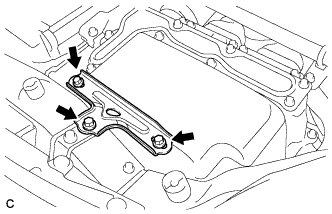
Remove the 3 bolts and No. 1 inverter bracket.
-
-
REMOVE HOOD LOCK SUPPORT SUB-ASSEMBLY
-
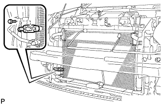
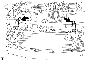
Disconnect the water by-pass hose clamp from the radiator support RH.
-
Disconnect the hood lock connector and hood lock control cable wire.
-
Disconnect the 3 wire harness clamps.
-
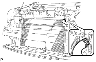
Disconnect the connector from the No. 2 cooling fan motor.
-
Disconnect the 2 wire harness clamps and connector from the fan shroud and cooling fan motor.
-
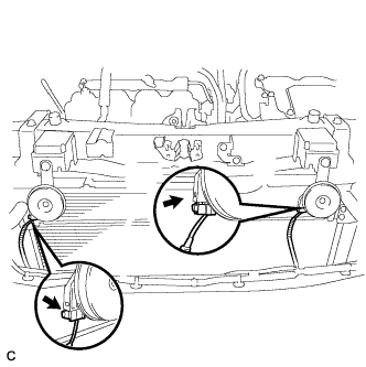
Disconnect the 2 horn connectors.
-
Remove the 2 bolts, radiator support RH and radiator support LH with the 2 cushions from the upper radiator support.
-
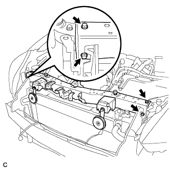
Remove the 4 bolts and upper radiator support.
-
-
REMOVE NO. 2 FAN SHROUD
-
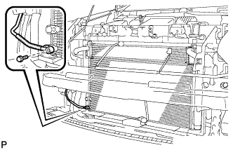
Disconnect the No. 1 water by-pass hose from the radiator assembly.
-
Disconnect the water by-pass hose from the radiator assembly.
-
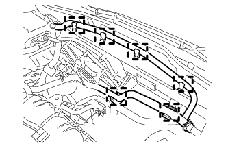
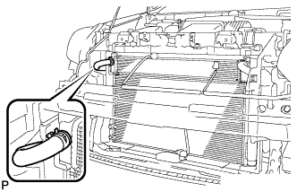
Disconnect the 6 water by-pass hose clamps from the No. 2 fan shroud.
-
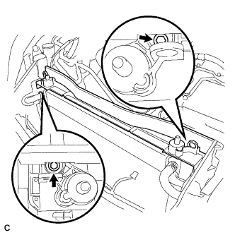
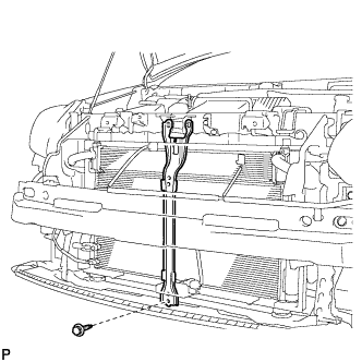
Remove the 2 bolts and No. 2 fan shroud from the radiator assembly.
-
-
REMOVE COOLER CONDENSER ASSEMBLY
-
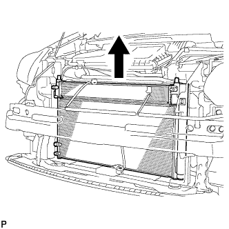
Remove the cooler condenser assembly with hybrid radiator assembly.
-
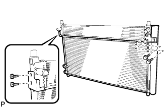
Remove the 4 bolts and cooler condenser assembly from the hybrid radiator assembly.
-