AIR CONDITIONING UNIT REASSEMBLY

-
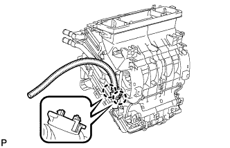
INSTALL NO. 1 COOLER THERMISTOR
-
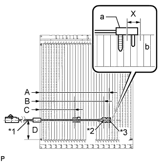
Text in Illustration *1 From Tank *2 Fixed Part *3 Sensor Part Install the No. 1 cooler thermistor as shown in the illustration.
Part Length A 175 mm 6.89 in. B 161.6 mm 6.36 in. C 87.9 mm 3.46 in. D 50 mm 1.99 in. Note
-
Be sure to insert the thermistor only once because reinserting it into the same position will not allow it to be firmly secured.
-
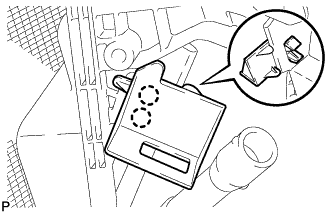
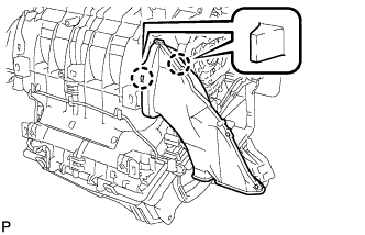
When reusing the evaporator, insert the thermistor one row next to the one that has been used previously (X in the illustration).
-
After inserting the thermistor, do not apply excessive force to the wire.
-
Directly insert the thermistor until the edge of plastic case "a" comes into contact with evaporator "b".
-
-
-
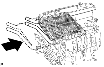
INSTALL COOLER EVAPORATOR SUB-ASSEMBLY
-
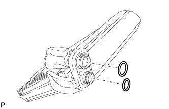
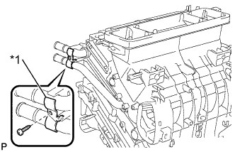
Sufficiently apply compressor oil to 2 new O-rings and the fitting surfaces.
Compressor oil ND-OIL 11 or equivalent -
Install the 2 O-rings to the cooler evaporator sub-assembly.
Note
-
Keep the O-rings and O-ring fitting surfaces clean from dirt or any foreign objects.
-
Do not use any compressor oil other than ND-OIL 11 or equivalent. If any compressor oil other than ND-OIL 11 or equivalent is used, compressor motor insulation performance may decrease, resulting in a leakage of electric power.
-
-
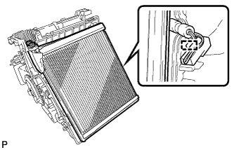
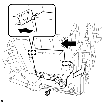
Engage the clamp and install the cooler evaporator sub-assembly with the No. 1 cooler thermistor.
Tech Tips
Completely cover the tube with the grommet.
-
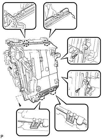
Engage the 4 claws.
-
Install the lower heater case with the 4 screws.
-
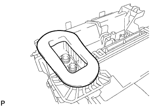
Install the packing.
-
-
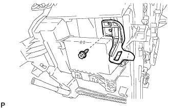
INSTALL COOLER EXPANSION VALVE
-
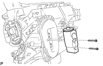
Using a 4 mm hexagon wrench, install the cooler expansion valve with the 2 hexagon bolts.
- Torque:
- 3.5 N*m { 36 kgf*cm, 31 in.*lbf }
-
-
INSTALL DRAIN COOLER HOSE
-
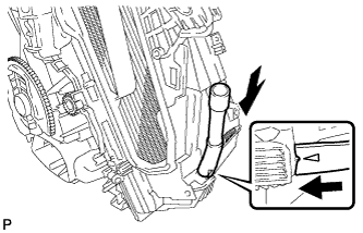
Install the drain cooler hose as shown in the illustration.
-
-
INSTALL CONSOLE MOUNTING BRACKET RH
-
Engage the 2 claws and install the console mounting bracket RH.
-
-
INSTALL AIR CONDITIONING AMPLIFIER ASSEMBLY
-
Engage the 2 guides to install the air conditioning amplifier assembly as shown in the illustration.
-
Install the screw.
-
-
INSTALL CONSOLE MOUNTING BRACKET LH
-
Install the console mounting bracket LH with the screw.
-
-
INSTALL HEATER RADIATOR UNIT SUB-ASSEMBLY
-
Install the heater radiator unit sub-assembly as shown in the illustration.
-
Text in Illustration *1 Clamp Install the clamp with the screw.
-
-
INSTALL QUICK HEATER ASSEMBLY (w/ PTC Heater)
-
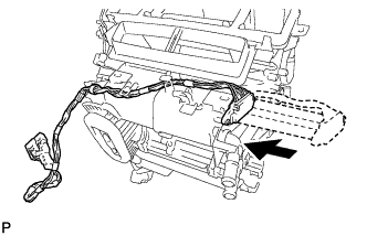
Install the quick heater assembly as shown in the illustration.
-
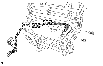
Install the 2 screws.
-
Engage each clamp.
-
-
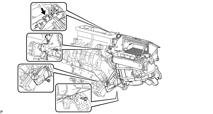
INSTALL AIR MIX CONTROL SERVO MOTOR SUB-ASSEMBLY
-
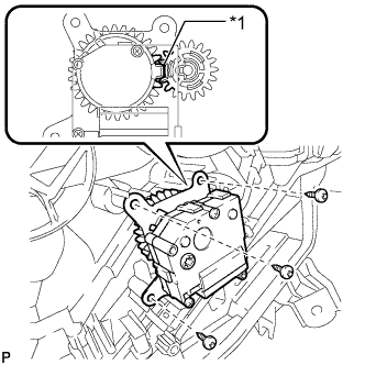
Text in Illustration *1 Reference Point Using the reference point, install the air mix control servo motor sub-assembly with the 3 screws.
-
-
INSTALL AIR OUTLET CONTROL SERVO MOTOR SUB-ASSEMBLY
-
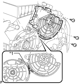
Text in Illustration *1 Reference Point Using the reference point, install the air outlet control servo motor sub-assembly with the 3 screws.
-
-
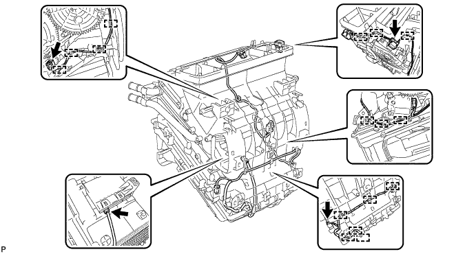
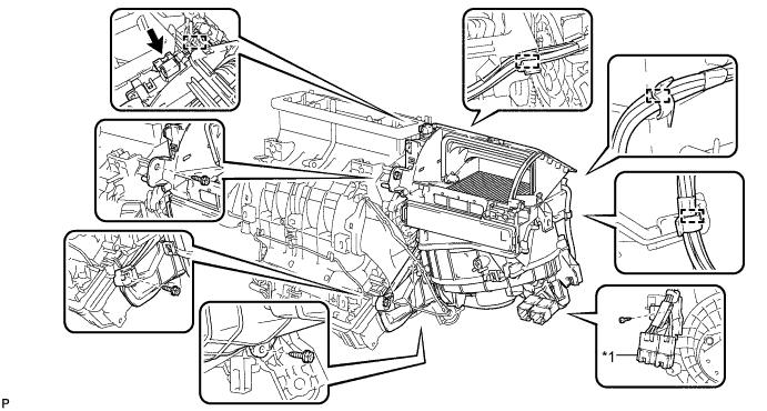
INSTALL AIR CONDITIONING HARNESS ASSEMBLY
-
Connect each connector.
-
Engage each clamp to install the air conditioning harness assembly.
-
-
INSTALL AIR CONDITIONING DUCT SUB-ASSEMBLY
-
Engage the 2 claws and install the air conditioning duct sub-assembly.
-
-
INSTALL NO. 1 AIR DUCT SUB-ASSEMBLY
-
Engage the 2 claws to install the No. 1 air duct sub-assembly.
-
-
INSTALL BLOWER ASSEMBLY
-
w/o PTC Heater:
-
Engage the guide.
-
Install the blower assembly with the 3 screws.
-
Connect the connector.
-
-
w/ PTC Heater:
-
Engage the guide.
-
Install the blower assembly with the 3 screws.
-
Connect the connector.
-
Engage each clamps.
-
Install the screw and connect the quick heater connector.
Text in Illustration *1 Quick Heater Connector - -
-
-