AIR CONDITIONING UNIT REMOVAL

-
PRECAUTION
Tech Tips
Before disconnecting the cable, set the air conditioning control switch to DEF-MODE. (for Automatic Air Conditioning System)
-
RECOVER REFRIGERANT FROM REFRIGERATION SYSTEM
-
Turn the A/C switch on.
-
Operate the A/C with the setting temperature at 25°C (77°F) and the blower level at LO for 10 minutes to circulate the refrigerant. This causes most of the compressor oil from the various components of the A/C system to collect in the A/C compressor.
-
Turn the power switch off.
-
Recover the refrigerant from the A/C system using a refrigerant recovery unit.
-
-
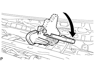
REMOVE WINDSHIELD WIPER MOTOR AND LINK ASSEMBLY
-
REMOVE COWL BODY MOUNTING REINFORCEMENT LH (for LHD)
-
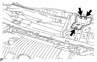
Remove the 3 bolts and cowl body mounting reinforcement LH.
-
-
REMOVE COWL BODY MOUNTING REINFORCEMENT LH (for RHD)
-
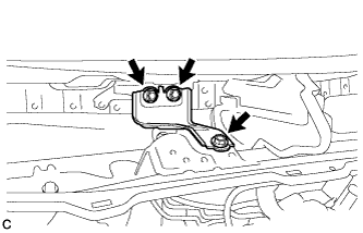
Remove the 3 bolts and cowl body mounting reinforcement LH.
-
-
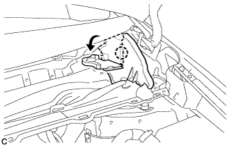
REMOVE OUTER COWL TOP PANEL SUB-ASSEMBLY (for LHD)
-
Disengage the clamp and separate the wire harness.
-
Disengage the claw and bend the No. 1 heater air duct splash shield seal.
-
Disengage the claw and bend the water guard plate RH.
-
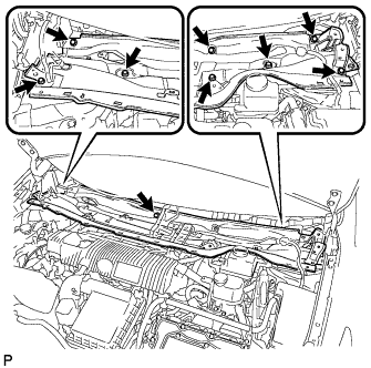
Remove the 9 bolts and outer cowl top panel sub-assembly.
-
-
REMOVE OUTER COWL TOP PANEL SUB-ASSEMBLY (for RHD)
-
Disengage the clamp and separate the wire harness from the outer cowl top panel sub-assembly.
-
Disengage the clamp*1 and disconnect the connector (w/ Windshield Deicer).
-
Disengage the clamp*2 and separate the wire harness from the outer cowl top panel sub-assembly.
-
Disengage the claw and bend the No. 1 heater air duct splash shield seal.
-
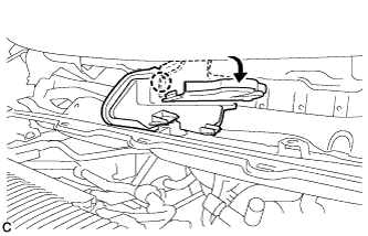
Disengage the claw and bend the water guard plate RH.
-
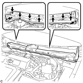
Remove the 9 bolts and outer cowl top panel sub-assembly.
-
-
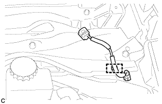
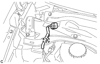
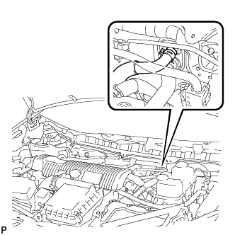
DISCONNECT SUCTION PIPE SUB-ASSEMBLY
-
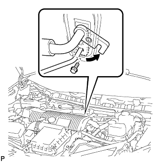
Remove the bolt and slide the hook connector.
-
Disconnect the suction pipe assembly.
-
Remove the O-ring from the suction pipe sub-assembly.
Note
Seal the openings of the disconnected parts using vinyl tape to prevent entry of moisture and foreign matter.
-
-
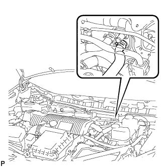
DISCONNECT AIR CONDITIONING TUBE AND ACCESSORY ASSEMBLY
-
Disconnect the air conditioning tube and accessory assembly.
-
Remove the O-ring from the air conditioning tube and accessory assembly.
Note
Seal the openings of the disconnected parts using vinyl tape to prevent entry of moisture and foreign matter.
-
-
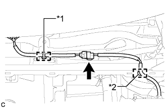
DISCONNECT INLET HEATER WATER HOSE
-
Using pliers, grip the claws of the clip and slide the clip to disconnect the inlet heater water hose.
Note
-
Do not apply excessive force to the inlet heater water hose.
-
Prepare a drain pan or cloth in case the coolant leaks.
-
-
-
DISCONNECT OUTLET HEATER WATER HOSE
-
Using pliers, grip the claws of the clip and slide the clip to disconnect the outlet heater water hose.
Note
-
Do not apply excessive force to the outlet heater water hose.
-
Prepare a drain pan or cloth in case the coolant leaks.
-
-
-
REMOVE LOWER INSTRUMENT PANEL SUB-ASSEMBLY
-
REMOVE HEADUP DISPLAY
-
Disconnect the connector.
-
Disengage the clamp.
-
Remove the bolt, 2 nuts and headup display.
-
-
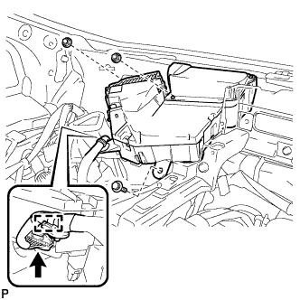
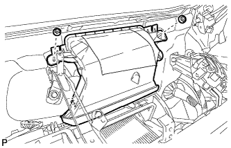
REMOVE ECU INTEGRATION BOX LH (for RHD)
-
Disconnect each connector.
-
Disengage the clamp and disconnect the wire harness.
-
Remove the bolt, nut and ECU integration box.
-
-
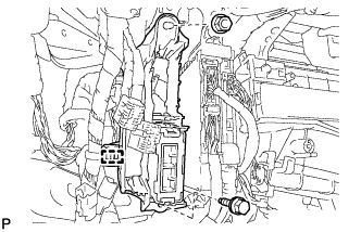
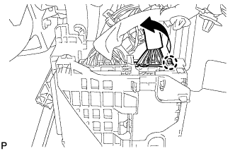
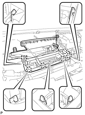
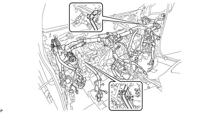
REMOVE DRIVER SIDE JUNCTION BLOCK ASSEMBLY (for LHD)
-
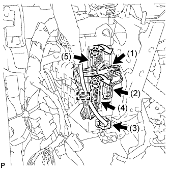
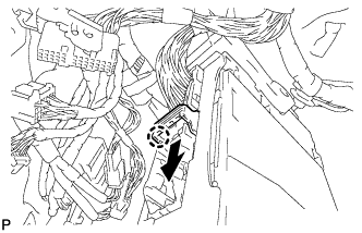
Disengage the clamp and disconnect the wire harness.
-
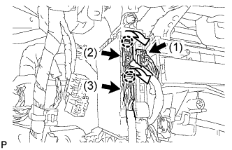
Disconnect the 3 connectors (1), (2) and (3).
-
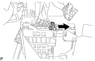
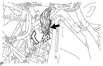
Disengage the 2 claws and disconnect the 2 connectors (4) and (5) as shown in the illustration.
-
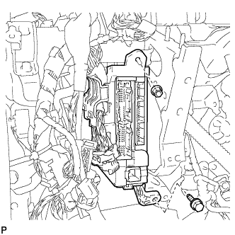
Remove the bolt and nut, and disconnect the driver side junction block assembly.
-
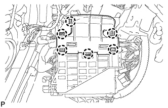
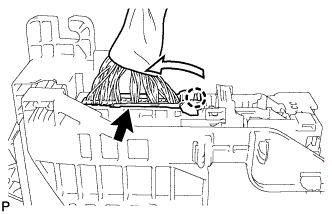
Disengage the 6 claws and remove the junction block bracket.
-
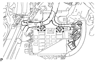
Disengage the 2 clamps and disconnect the wire harness.
-
Disengage the claw and disconnect the connector as shown in the illustration.
-
Disengage the claw and release the connector lock as shown in the illustration.
-
Disengage the claw and disconnect the connector as shown in the illustration.
-
Remove the driver side junction block assembly.
-
-
REMOVE FRONT PASSENGER SIDE JUNCTION BLOCK ASSEMBLY (for RHD)
-
Disconnect the connector (1).
-
Disengage the 2 claws and disconnect the connector (2) and (3) as shown in the illustration.
-

Disengage the 2 clamps and disconnect the wire harness.
-
Remove the bolt and nut, and disconnect the front passenger side junction block assembly.
-

Disengage the clamp and disconnect the wire harness.
-
Disengage the claw and disconnect the connector as shown in the illustration.
-
Disengage the claw and release the connector lock as shown in the illustration.
-
Disengage the claw and disconnect the connector as shown in the illustration.
-
Remove the front passenger side junction block assembly.
-
-
REMOVE STEERING POST ASSEMBLY
-
REMOVE REAR NO. 2 AIR DUCT
-
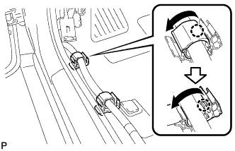
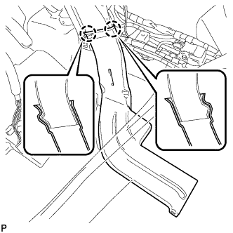
Disengage each claw to open the 2 door scuff plate clamps as shown in the illustration.
-
Disengage the clip and fastener.
-
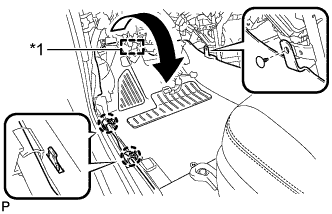
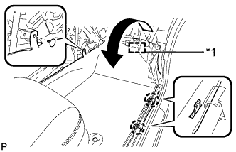
Disengage the 2 claws and turn back the floor carpet as shown in the illustration.
Text in Illustration *1 Fastener -
Disengage the 2 claws and remove the rear No. 2 air duct.
-
-
REMOVE REAR NO. 3 AIR DUCT
-
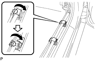
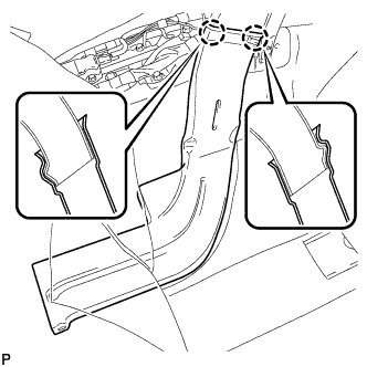
Disengage each claw to open the 2 door scuff plate clamps as shown in the illustration.
-
Disengage the clip and fastener.
-
Disengage the 2 claws and turn back the floor carpet as shown in the illustration.
Text in Illustration *1 Fastener -
Disengage the 2 claws and remove the rear No. 3 air duct.
-
-
REMOVE REAR NO. 1 AIR DUCT
-
Disengage the 4 claws and remove the rear No. 1 air duct.
-
-
REMOVE NO. 3 SIDE DEFROSTER NOZZLE DUCT
-
Remove the clip and No. 3 side defroster nozzle duct.
-
-
REMOVE NO. 1 INSTRUMENT PANEL BRACE SUB-ASSEMBLY
-
Check that the power switch is off.
-
Check that the cable is disconnected from the negative (-) battery terminal.
CAUTION:
Wait at least 90 seconds after disconnecting the cable from the negative (-) battery terminal to disable the SRS system.
-
Disconnect the center airbag sensor connectors from the center airbag sensor assembly as shown in the illustration.
Note
When disconnecting any airbag connector, take care not to damage the airbag wire harness.
-
Remove the screw.
-
Remove the 2 bolts and disconnect the 2 earth wires.
-
Disconnect each connector.
-
Disengage each clamp and claw.
Text in Illustration *1 Center airbag sensor connector *2 Screw *3 Bolt *4 Earth wires -
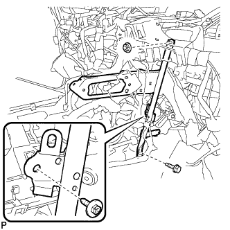
Remove the screw.
-
Remove the bolt, nut and No. 1 instrument panel brace sub-assembly.
-
-
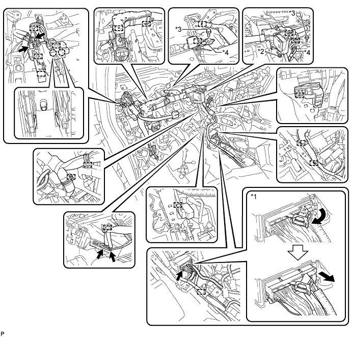
REMOVE NO. 2 INSTRUMENT PANEL BRACE SUB-ASSEMBLY
-
Remove the 3 screws <A>.
-
Remove the bolt and disconnect the earth wire.
-
Disconnect each connector.
-
Disengage each clamp.
-
Remove the screw <B> and 2 nuts from the computer integration box RH.
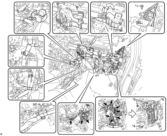
Text in Illustration *1 Screw <A> *2 Bolt *3 Earth wires *4 Screw <B> *5 Nut *6 Computer integration box RH -
Remove the screw.
-
Remove the bolt, nut and No. 2 instrument panel brace sub-assembly.
-
-
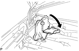
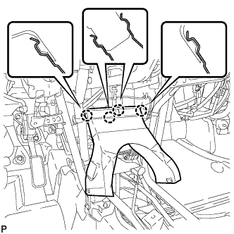
REMOVE DEFROSTER NOZZLE ASSEMBLY
-
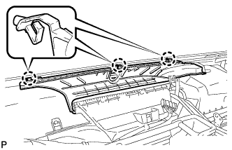
Disengage the 3 claws.
-
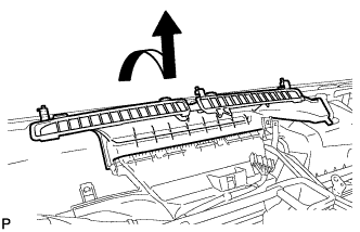
Remove the defroster nozzle assembly as shown in the illustration.
-
-
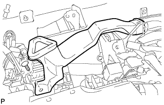
REMOVE LOWER DEFROSTER NOZZLE ASSEMBLY
-
Disengage the clamp.
-
Disengage the 6 claws and remove the lower defroster nozzle assembly.
-
-
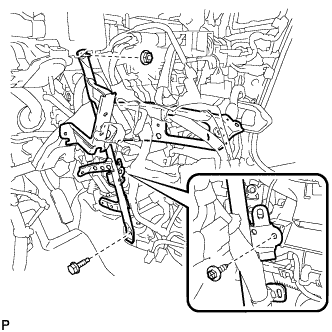
REMOVE NO. 3 AIR DUCT SUB-ASSEMBLY
-
Remove the 2 nuts and No. 3 air duct sub-assembly.
-
-
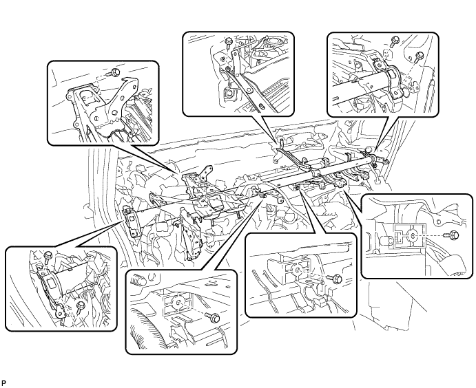
REMOVE INSTRUMENT PANEL REINFORCEMENT ASSEMBLY
-
Disengage each clamp.
-
Remove the 9 bolts and instrument panel reinforcement assembly.
-
-
REMOVE AIR CONDITIONING UNIT ASSEMBLY
Note
-
Be sure to support the air conditioning unit assembly when removing it because failure to do so may cause the bracket of the air conditioning unit assembly to break.
-
When disassembling the air conditioning unit, eliminate static electricity by touching the vehicle body to prevent the components from being damaged.
-
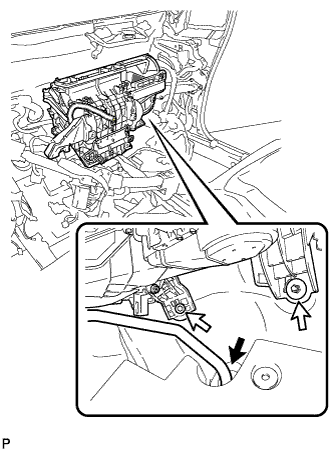
Disconnect the drain cooler hose.
-
Remove the bolt, nut and air conditioning unit assembly.
-