AIR CONDITIONING UNIT REMOVAL

-
PRECAUTION
Note
After the power switch is turned off, the display and navigation module display (HDD navigation system) records various types of memory and settings. As a result, after turning the power switch off, make sure to wait at least 60 seconds before disconnecting the cable from the negative (-) battery terminal.
Tech Tips
Before disconnecting the cable, set the air conditioning control switch to DEF-MODE. (for Automatic Air Conditioning System)
-
RECOVER REFRIGERANT FROM REFRIGERATION SYSTEM
-
Turn the A/C switch on.
-
Operate the A/C with the setting temperature at 25°C (77°F) and the blower level at LO for 10 minutes to circulate the refrigerant. This causes most of the compressor oil from the various components of the A/C system to collect in the A/C compressor.
-
Turn the power switch off.
-
Recover the refrigerant from the A/C system using a refrigerant recovery unit.
-
-
ALIGN FRONT WHEELS STRAIGHT AHEAD
-
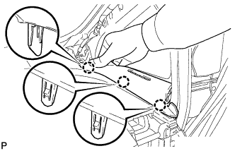
REMOVE REAR NO. 2 FLOOR BOARD
-

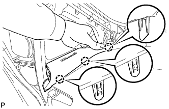
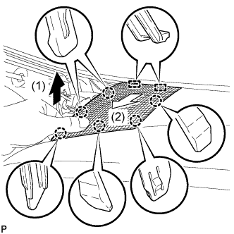
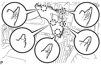
Disengage the 2 guides <A> as shown in the illustration.
-
Disengage the 3 guides <B> and remove the rear No. 2 floor board.
-
-
REMOVE REAR DECK FLOOR BOX
-
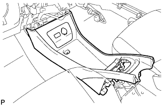
Remove the rear deck floor box.
-
-
REMOVE REAR NO. 3 FLOOR BOARD
-

Disengage the 2 guides and remove the rear No. 3 floor board.
-
-
DISCONNECT CABLE FROM NEGATIVE BATTERY TERMINAL
CAUTION:
Wait at least 90 seconds after disconnecting the cable from the negative (-) battery terminal to disable the SRS system.
Note
When disconnecting the cable, some systems need to be initialized after the cable is reconnected Click here.
-
REMOVE FRONT WIPER ARM HEAD CAP
-
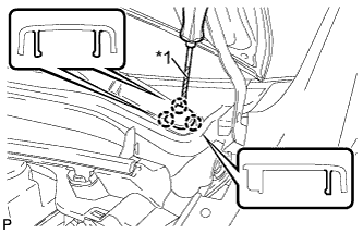
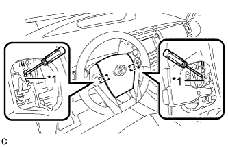
Text in Illustration *1 Protective Tape Using a screwdriver, disengage the 3 claws to remove the front wiper arm head cap.
Tech Tips
-
Tape the screwdriver tip before use.
-
Use the same procedure for the RH side and LH side.
-
-
-
REMOVE FRONT WIPER ARM AND BLADE ASSEMBLY LH
-
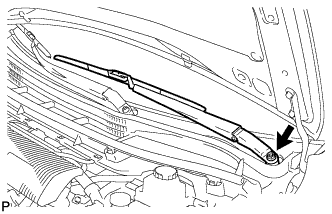
Remove the nut and the front wiper arm and blade assembly LH.
-
-
REMOVE FRONT WIPER ARM AND BLADE ASSEMBLY RH
-
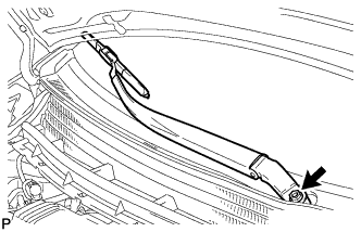
Remove the nut and the front wiper arm and blade assembly RH.
-
-
REMOVE COWL SIDE VENTILATOR SUB-ASSEMBLY LH
-
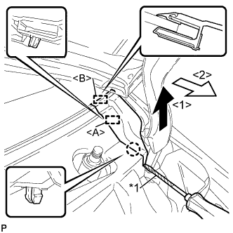
Text in Illustration *1 Protective Tape Using a screwdriver, disengage the claw and guide <A> as shown in the illustration.
Tech Tips
Tape the screwdriver tip before use.
-
Disengage the guide <B> and remove the cowl side ventilator sub-assembly LH as shown in the illustration.
-
-
REMOVE COWL SIDE VENTILATOR SUB-ASSEMBLY RH
Tech Tips
Use the same procedure as for the LH side.
-
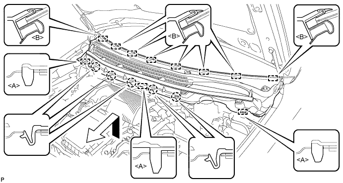
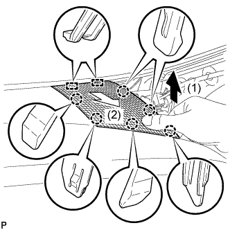
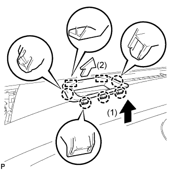
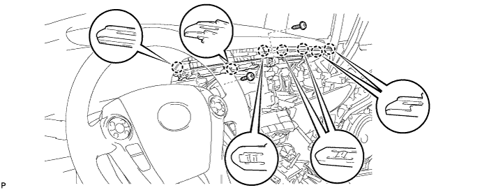
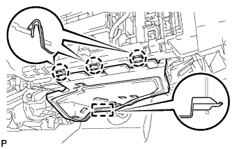
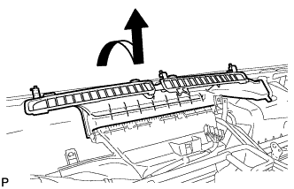
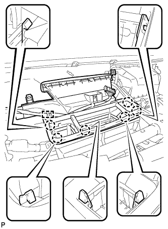
REMOVE COWL TOP VENTILATOR LOUVER SUB-ASSEMBLY (for LHD)
-
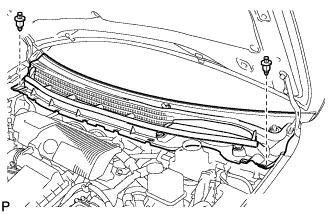
Remove the 2 clips.
-
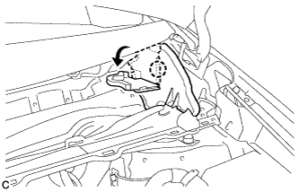
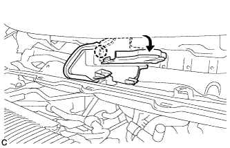
Disengage the 5 claws and 3 guides <A>.
-
Disengage the 8 guides <B> and pull out the cowl top ventilator louver sub-assembly as shown in the illustration.
-
-
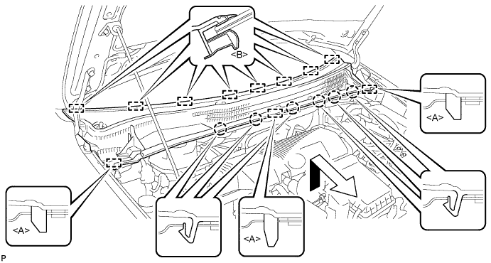
REMOVE COWL TOP VENTILATOR LOUVER SUB-ASSEMBLY (for RHD)
-
Remove the 2 clips.
-
Disengage the 6 claws and 3 guides <A>.
-
Disengage the 8 guides <B> and pull out the cowl top ventilator louver sub-assembly as shown in the illustration.
-
-
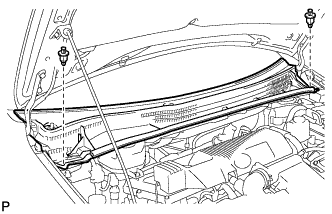
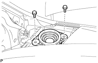
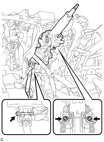
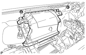
REMOVE WINDSHIELD WIPER MOTOR AND LINK ASSEMBLY
-
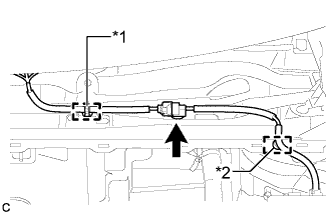
Disengage the 2 clamps.
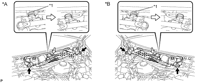
Text in Illustration *A for LHD: *B for RHD: *1 Grommet - - -
Remove the 2 bolts.
-
Disengage the grommet as shown in the illustration.
-
Disconnect the connector.
-
Remove the windshield wiper motor and link assembly.
Note
Be careful not to damage the windshield when removing the windshield wiper motor and link assembly.
-
-
REMOVE COWL BODY MOUNTING REINFORCEMENT LH (for LHD)
-
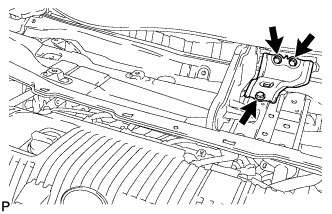
Remove the 3 bolts and cowl body mounting reinforcement LH.
-
-
REMOVE COWL BODY MOUNTING REINFORCEMENT LH (for RHD)
-
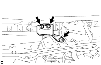
Remove the 3 bolts and cowl body mounting reinforcement LH.
-
-
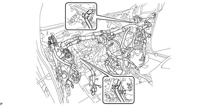
REMOVE OUTER COWL TOP PANEL SUB-ASSEMBLY (for LHD)
-
Disengage the clamp and separate the wire harness.
-
Disengage the claw and bend the No. 1 heater air duct splash shield seal.
-
Disengage the claw and bend the water guard plate RH.
-
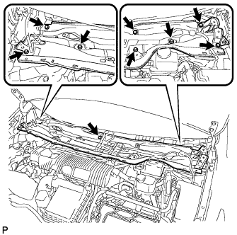
Remove the 9 bolts and outer cowl top panel sub-assembly.
-
-
REMOVE OUTER COWL TOP PANEL SUB-ASSEMBLY (for RHD)
-
Disengage the clamp and separate the wire harness from the outer cowl top panel sub-assembly.
-
Disengage the clamp*1 and disconnect the connector (w/ Windshield Deicer).
-
Disengage the clamp*2 and separate the wire harness from the outer cowl top panel sub-assembly.
-
Disengage the claw and bend the No. 1 heater air duct splash shield seal.
-
Disengage the claw and bend the water guard plate RH.
-
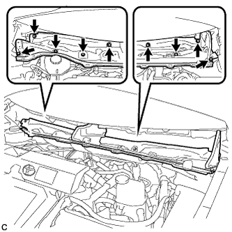
Remove the 9 bolts and outer cowl top panel sub-assembly.
-
-
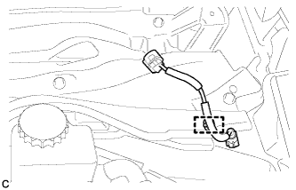
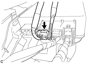
DISCONNECT SUCTION PIPE SUB-ASSEMBLY
-
Remove the bolt and slide the hook connector.
-
Disconnect the suction pipe assembly.
-
Remove the O-ring from the suction pipe sub-assembly.
Note
Seal the openings of the disconnected parts using vinyl tape to prevent entry of moisture and foreign matter.
-
-
DISCONNECT AIR CONDITIONING TUBE AND ACCESSORY ASSEMBLY
-
Disconnect the air conditioning tube and accessory assembly.
-
Remove the O-ring from the air conditioning tube and accessory assembly.
Note
Seal the openings of the disconnected parts using vinyl tape to prevent entry of moisture and foreign matter.
-
-
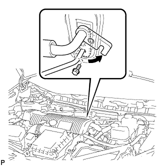
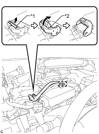
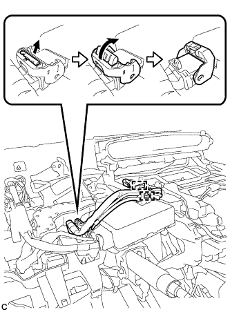
DISCONNECT INLET HEATER WATER HOSE
-
Using pliers, grip the claws of the clip and slide the clip to disconnect the inlet heater water hose.
Note
-
Do not apply excessive force to the inlet heater water hose.
-
Prepare a drain pan or cloth in case the coolant leaks.
-
-
-
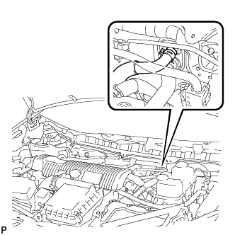
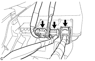
DISCONNECT OUTLET HEATER WATER HOSE
-
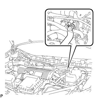
Using pliers, grip the claws of the clip and slide the clip to disconnect the outlet heater water hose.
Note
-
Do not apply excessive force to the outlet heater water hose.
-
Prepare a drain pan or cloth in case the coolant leaks.
-
-
-
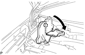
REMOVE INTEGRATION CONTROL AND PANEL ASSEMBLY
-
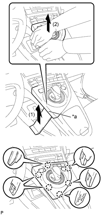
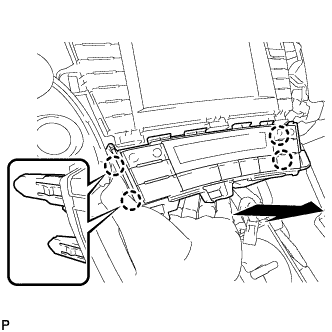
Text in Illustration *a Lift slightly Using a moulding remover, slightly lift the panel at the position shown in the illustration.
-
Pull the integration control and panel assembly in the direction indicated by the arrow to disengage the 6 claws.
-
Disconnect each connector and remove the integration control and panel assembly.
-
-
REMOVE LOWER CENTER INSTRUMENT CLUSTER FINISH PANEL SUB-ASSEMBLY
-
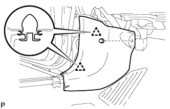
Pull the lower center instrument cluster finish panel sub-assembly in the direction indicated by the arrow to disengage the 2 claws and 2 clips.
-
Pull the lower center instrument cluster finish panel sub-assembly in the direction indicated by the arrow to disengage the 5 claws and remove the lower center instrument cluster finish panel sub-assembly.
-
-
REMOVE INSTRUMENT CLUSTER FINISH PANEL GARNISH
-
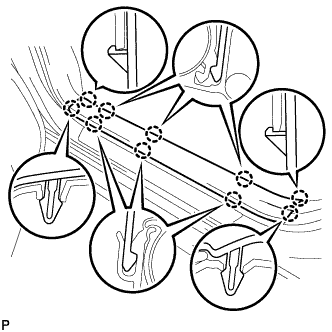
Disengage the 14 claws.
-
Disconnect the connector and remove the instrument cluster finish panel garnish.
-
-
REMOVE UPPER INSTRUMENT PANEL FINISH PANEL SUB-ASSEMBLY
-
Disengage the 3 claws.
-
Disconnect the connector and remove the upper instrument panel finish panel sub-assembly.
-
-
REMOVE CENTER INSTRUMENT CLUSTER FINISH PANEL SUB-ASSEMBLY (w/o Radio Receiver)
-
Disengage the 4 claws and remove the center instrument cluster finish panel sub-assembly.
-
-
REMOVE RADIO TUNER OPENING COVER WITH BRACKET (w/o Radio Receiver)
-
Remove the 4 bolts <B> and radio tuner opening cover with bracket.
-
-
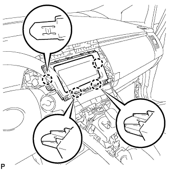
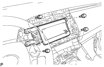
REMOVE RADIO AND DISPLAY RECEIVER ASSEMBLY WITH BRACKET (for Radio and Display Type)
-
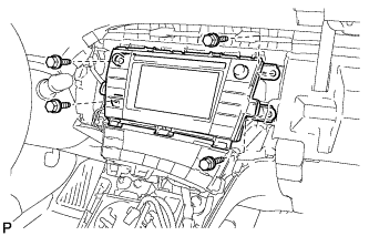
Remove the 4 bolts.
-
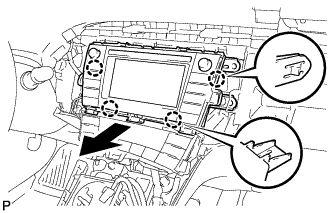
Disengage the 4 claws as shown in the illustration.
-
Disconnect each connector and remove the radio and display receiver assembly with bracket.
-
-
REMOVE NAVIGATION RECEIVER WITH BRACKET (for Navigation Receiver Type)
-
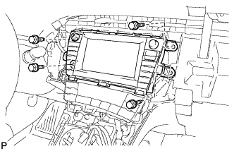
Remove the 4 bolts.
-
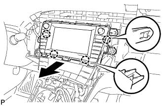
Disengage the 4 claws and remove the navigation receiver with bracket as shown in the illustration.
-
Disconnect each connector.
-
-
REMOVE FRONT DOOR SCUFF PLATE LH
-
Disengage the 10 claws and remove the front door scuff plate LH.
-
-
REMOVE COWL SIDE TRIM SUB-ASSEMBLY LH
-
Remove the clip.
-
Disengage the 2 clips and remove the cowl side trim sub-assembly LH.
-
-
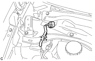
REMOVE LOWER INSTRUMENT PANEL FINISH PANEL ASSEMBLY
-
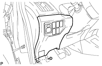
Remove the screw <C>.
-
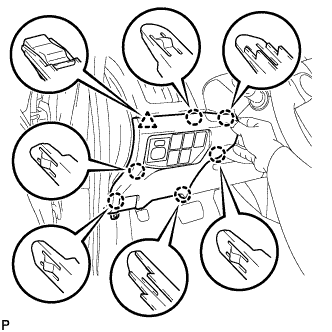
Disengage the 6 claws and clip as shown in the illustration.
-
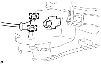
Disengage the claw and 2 guides and disconnect the hood lock control cable.
-
Disconnect each connector and clamp, and remove the lower instrument panel finish panel assembly.
-
-
REMOVE NO. 1 INSTRUMENT PANEL REGISTER
-
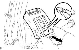
Pull the No. 1 instrument panel register in the direction indicated by the arrow to disengage the 2 claws.
-
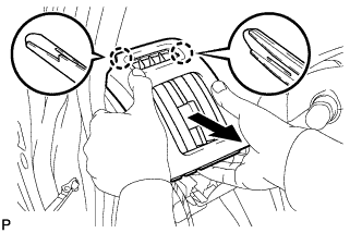
Pull the No. 1 instrument panel register in the direction indicated by the arrow to disengage the 2 claws and remove the No. 1 instrument panel register.
-
-
REMOVE NO. 1 CENTER INSTRUMENT CLUSTER FINISH PANEL
-
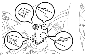
Disengage the 4 claws to remove the No. 1 center instrument cluster finish panel.
-
-
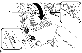
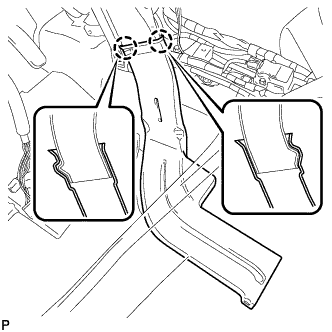
DISCONNECT FRONT DOOR OPENING TRIM WEATHERSTRIP LH
-
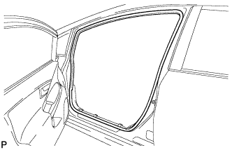
Remove the front door opening trim weatherstrip LH.
-
-
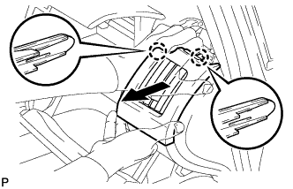
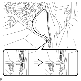
REMOVE INSTRUMENT PANEL FINISH PANEL END LH
-
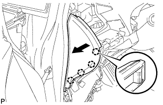
Pull the instrument panel finish panel end LH in the direction indicated by the arrow to disengage the 4 claws.
-
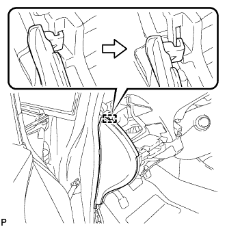
Disengage the guide as shown in the illustration.
-
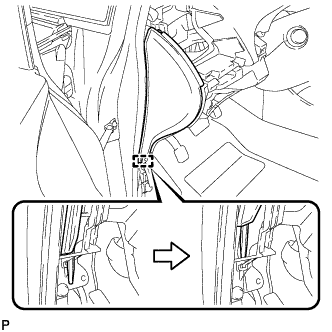
Disengage the guide and remove the instrument panel finish panel end LH as shown in the illustration.
-
-
REMOVE NO. 1 SIDE DEFROSTER NOZZLE
-
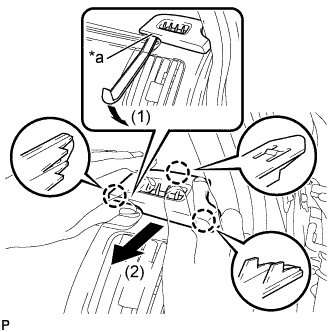
Text in Illustration *a Lift slightly Using a moulding remover, slightly lift the panel at the position shown in the illustration.
-
Pull the No. 1 side defroster nozzle in the direction indicated by the arrow to disengage the 3 claws and remove the No. 1 side defroster nozzle.
-
-
REMOVE NO. 2 INSTRUMENT PANEL REGISTER
-
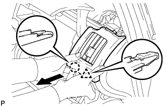
Pull the No. 2 instrument panel register in the direction indicated by the arrow to disengage the claw and clip.
-
Pull the No. 2 instrument panel register in the direction indicated by the arrow to disengage the 2 claws and remove the No. 2 instrument panel register.
-
-
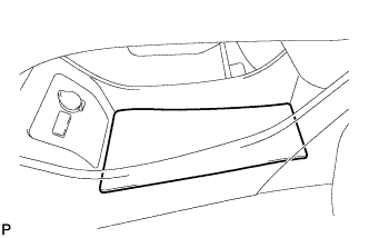
REMOVE GLOVE COMPARTMENT DOOR
-
Open the glove compartment door assembly.
-
Pull the glove compartment door in the direction indicated by the arrow to disengage the 7 claws.
-
Pull the glove compartment door in the direction indicated by the arrow to remove the glove compartment door.
-
-
REMOVE FRONT DOOR OPENING TRIM WEATHERSTRIP RH
Tech Tips
Use the same procedure for the RH side and LH side.
-
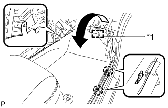
REMOVE INSTRUMENT PANEL FINISH PANEL END RH
-
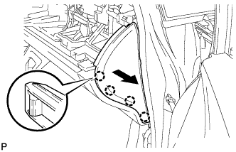
Pull the instrument panel finish panel end RH in the direction indicated by the arrow to disengage the 4 claws.
-
Disengage the guide as shown in the illustration.
-
w/o Airbag Cut Off Switch:
-
Disengage the guide and remove the instrument panel finish panel end RH as shown in the illustration.
-
-
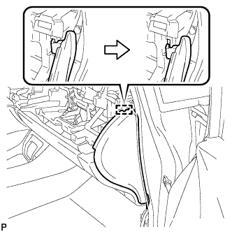
w/ Airbag Cut Off Switch:
-
Disengage the guide.
-
Disconnect the connector and remove the instrument panel finish panel end RH as shown in the illustration.
-
-
-
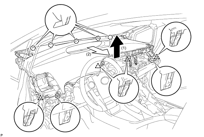
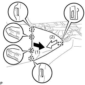
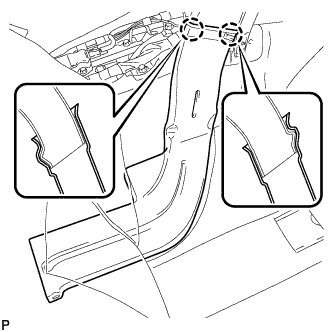
REMOVE FRONT PILLAR GARNISH LH
-
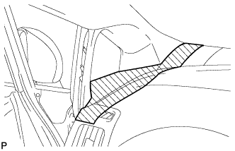
When removing the front pillar garnish LH, cover the shaded part in the illustration with a piece of cloth so that the interior parts will not be damaged.
-
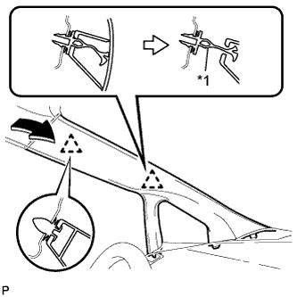
Text in Illustration *1 Front Pillar Garnish Clip Pull the upper part of the garnish toward the inside of the cabin and disengage the 2 clips.
Tech Tips
Make the front pillar garnish LH hang down from the front pillar garnish clip.
-
Turn the end of the front pillar garnish clip 90° with needle-nosed pliers and remove it from the front pillar garnish LH.
Note
-
Front pillar garnish clips are reusable if they are not removed from the vehicle and have no damage.
-
Replace the front pillar garnish clips with new ones if they are removed from the vehicle.
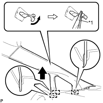
Tech Tips
Tape the needle-nosed pliers tip before use.
Text in Illustration *1 Protective Tape -
-
Disengage the 3 guides.
-
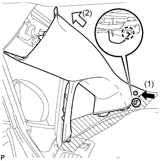
Disengage the claw while pressing the shaded part in the illustration in the direction indicated by the arrow (1).
-
Remove the front pillar garnish LH by pulling it in the direction indicated by the arrow (2) in the illustration.
-
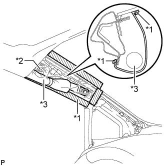
Text in Illustration *1 Adhesive Tape *2 Protective Cover *3 Curtain Shield Airbag Assembly Protect the curtain shield airbag assembly.
-
Cover the airbag with a cloth or piece of nylon and secure the ends of the cover with tape as shown in the illustration.
Note
Cover the curtain shield airbag with a protective cover as soon as the front pillar garnish is removed.
-
-
-
REMOVE FRONT PILLAR GARNISH CORNER PIECE LH
-
Disengage the 3 claws and front pillar garnish corner piece LH as shown in the illustration.
-
-
REMOVE NO. 1 INSTRUMENT PANEL SPEAKER PANEL SUB-ASSEMBLY
-
Pull the No. 1 instrument panel speaker panel sub-assembly in the direction indicated by the arrow to disengage the 6 claws and 2 guides, and remove the No. 1 instrument panel speaker panel sub-assembly.
-
-
REMOVE FRONT NO. 2 SPEAKER ASSEMBLY
-
Remove the 2 bolts.
-
Disconnect the connector and remove the front No. 2 speaker assembly.
Note
Do not touch the cone part of the speaker.
-
-
REMOVE FRONT PILLAR GARNISH RH
Tech Tips
Use the same procedure for the RH side and LH side.
-
REMOVE FRONT PILLAR GARNISH CORNER PIECE RH
-
Disengage the 3 claws and front pillar garnish corner piece RH as shown in the illustration.
-
-
REMOVE NO. 2 INSTRUMENT PANEL SPEAKER PANEL SUB-ASSEMBLY
-
Pull the No. 2 instrument panel speaker panel sub-assembly in the direction indicated by the arrow to disengage the 6 claws and 2 guides, and remove the No. 2 instrument panel speaker panel sub-assembly.
-
-
REMOVE FRONT NO. 2 SPEAKER ASSEMBLY
Tech Tips
Use the same procedure for the RH side and LH side.
-
REMOVE INSTRUMENT CLUSTER FINISH PANEL END
-
Pull the instrument cluster finish panel end in the direction indicated by the arrow to disengage the 5 claws and 2 guides, and remove the instrument cluster finish panel end.
-
-
REMOVE CENTER INSTRUMENT CLUSTER FINISH PANEL GARNISH
-
Remove the 2 screws <C>.
-
Disengage the 7 claws.
-
Disconnect the connector and remove the center instrument cluster finish panel garnish.
-
-
DISCONNECT NO. 3 INSTRUMENT PANEL WIRE
-
Check that the power switch is off.
-
Check that the cable is disconnected from the negative (-) battery terminal.
CAUTION:
Wait at least 90 seconds after disconnecting the cable from the negative (-) battery terminal to disable the SRS system.
-
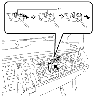
Text in Illustration *1 Slider Slide the slider to release the lock, and then disconnect the connector.
Note
When disconnecting any airbag connector, take care not to damage the airbag wire harness.
-
-
REMOVE UPPER INSTRUMENT PANEL ASSEMBLY
-
Disconnect each connector.
-
Disengage the 2 clamps.
-
Remove the 2 bolts <B>.
-
Remove the 2 passenger airbag bolts <A>.
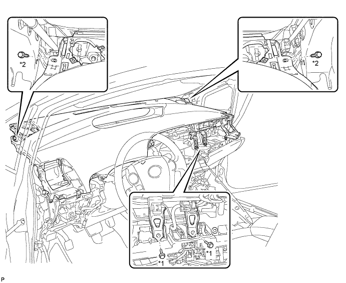
Text in Illustration *1 Passenger Airbag Bolt <A> *2 Bolt <B> -
Pull the upper instrument panel assembly in the direction indicated by the arrow to disengage the 2 claws and 4 clips.
-
Pull the upper instrument panel assembly in the direction indicated by the arrow to disengage the 5 claws and remove the upper instrument panel assembly.
-
-
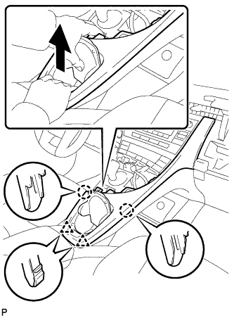
REMOVE REAR CONSOLE BOX CUP HOLDER
-
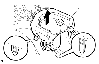
Disengage the 4 claws and remove the rear console box cup holder as shown in the illustration.
-
-
REMOVE CONSOLE BOX CARPET
-
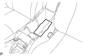
Remove the console box carpet.
-
-
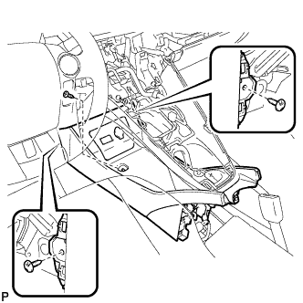
REMOVE REAR CONSOLE BOX ASSEMBLY
-
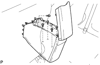
Remove the 5 bolts.
-
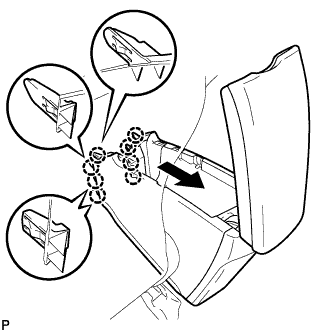
Pull the rear console box assembly in the direction indicated by the arrow to disengage the 8 claws.
-
Disconnect each connector and remove the rear console box assembly.
-
-
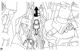
REMOVE ELECTRICAL KEY OSCILLATOR
-
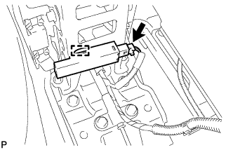
Disconnect the connector.
-
Disengage the clamp and remove the electrical key oscillator.
Note
Be careful when removing the electrical key oscillator. If the oscillator is dropped, replace it with a new one.
-
-
REMOVE NO. 2 CONSOLE BOX MOUNTING BRACKET
-
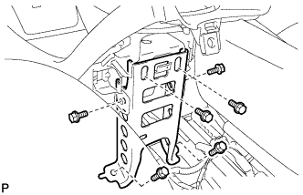
Remove the 6 bolts <B> and No. 2 console box mounting bracket.
-
-
REMOVE FRONT NO. 1 CONSOLE BOX INSERT
-
Pull the front No. 1 console box insert in the direction indicated by the arrow to disengage the 4 claws and guide, and remove the front No. 1 console box insert.
-
-
REMOVE FRONT NO. 2 CONSOLE BOX INSERT
-
Pull the front No. 2 console box insert in the direction indicated by the arrow to disengage the 4 claws and guide, and remove the front No. 2 console box insert.
-
-
REMOVE BOX BOTTOM MAT
-
Disengage the fastener and remove the box bottom mat.
-
-
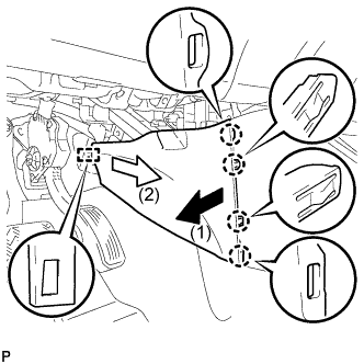
SEPARATE CONSOLE BOX ASSEMBLY
-
Remove the bolt <B> and 2 clips.
-
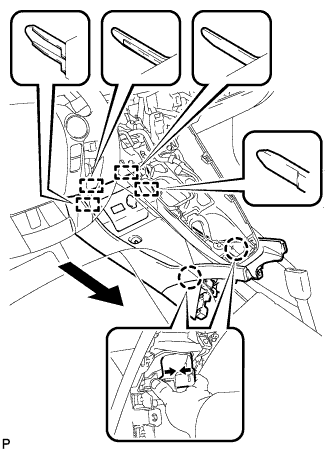
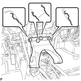
While pushing the parts shown in the illustration inward, pull the console box assembly in the direction indicated by the arrow to disengage the 2 claws and 4 guides.
-
Disconnect the connector and separate the console box assembly.
-
-
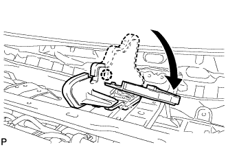
REMOVE AIR CONDITIONING CONTROL ASSEMBLY
-
Disengage the 4 claws and remove the air conditioning control assembly as shown in the illustration.
-
Disconnect the connector.
Note
Since the connectors for the air conditioning control assembly and the integration control and panel sub-assembly are the same shape, mark them so that they will not be reconnected incorrectly.
-
-
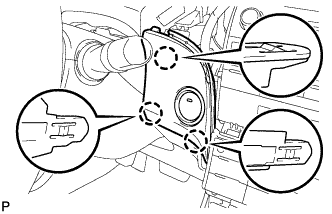
REMOVE SHIFT LOCK CONTROL UNIT ASSEMBLY
-
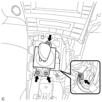
Disconnect the connector from the shift lock control unit assembly.
-
Remove the 3 nuts and shift lock control unit assembly.
-
-
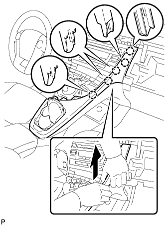
REMOVE UPPER INSTRUMENT PANEL FINISH PANEL ASSEMBLY
-
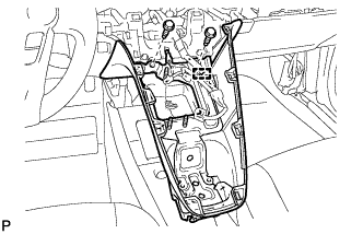
Disengage the clamp.
-
Remove the 2 bolts <A>.
-
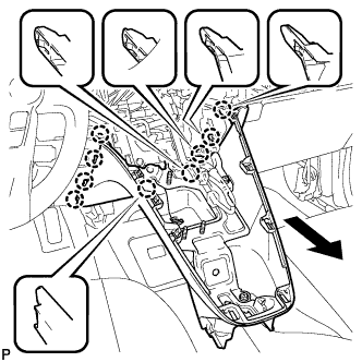
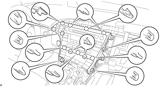
Pull the upper instrument panel finish panel assembly in the direction indicated by the arrow to disengage the 9 claws and remove the upper instrument panel finish panel assembly.
-
-
REMOVE CONSOLE BOX ASSEMBLY
-
Remove the console box assembly.
-
-
REMOVE NO. 1 SWITCH HOLE BASE
-
Disengage the 5 claws.
-
Disconnect the connector to remove the No. 1 switch hole base.
-
-
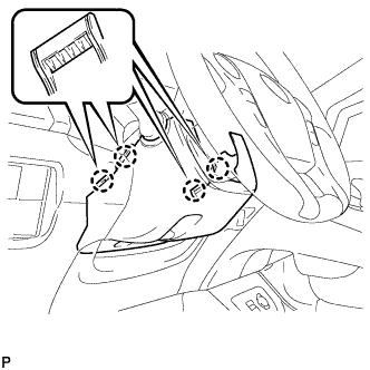
REMOVE LOWER NO. 3 STEERING WHEEL COVER
-
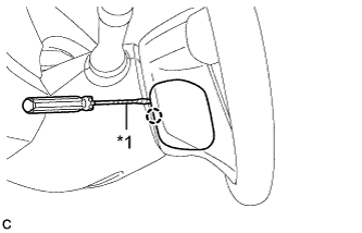
Text in Illustration *1 Protective Tape Using a screwdriver with its tip wrapped with protective tape, disengage the claw to remove the lower No. 3 steering wheel cover.
-
-
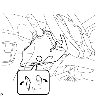
REMOVE LOWER NO. 2 STEERING WHEEL COVER
-
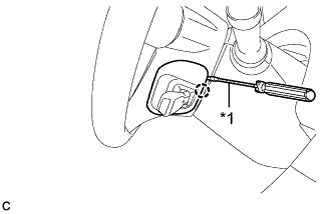
Text in Illustration *1 Protective Tape Using a screwdriver with its tip wrapped with protective tape, disengage the claw to remove the lower No. 2 steering wheel cover.
-
-
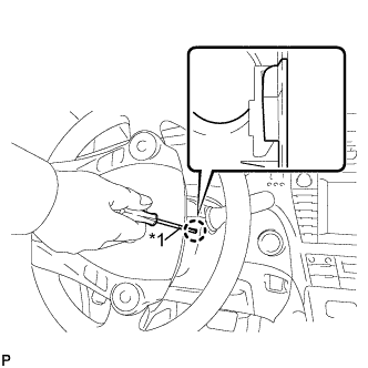
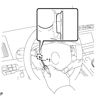
REMOVE STEERING PAD
CAUTION:
When storing the steering pad, keep the airbag deployment side facing upward.
-
Check that the power switch is off.
-
Check that the cable is disconnected from the negative (-) battery terminal.
CAUTION:
Wait at least 90 seconds after disconnecting the cable from the negative (-) battery terminal to disable the SRS system.
-
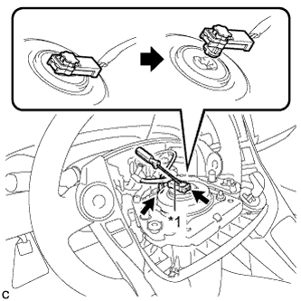
Text in Illustration *1 Torsional Spring Using a screwdriver, push the torsional spring to disengage the 2 pins.
-
Text in Illustration *1 Protective Tape Pull out the steering pad from the steering wheel assembly and support the steering pad with one hand.
Note
When removing the steering pad, do not pull the airbag wire harness.
-
Disconnect the horn connector from the steering pad.
-
Using a screwdriver with its tip wrapped with protective tape, release the airbag connector lock.
-
Disconnect the airbag connector to remove the steering pad.
Note
When disconnecting any airbag connector, take care not to damage the airbag wire harness.
-
-
REMOVE STEERING WHEEL ASSEMBLY
-
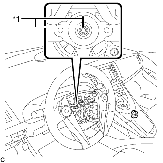
Text in Illustration *1 Matchmark Remove the steering wheel assembly set nut.
-
Put matchmarks on the steering wheel assembly and steering main shaft.
-
Disconnect the connectors from the spiral cable.
-
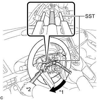
Text in Illustration *1 Turn *2 Hold Using SST, remove the steering wheel assembly.
- SST
- 09950-50013 ( 09951-05010, 09952-05010, 09953-05020, 09955-04071 )
Note
Apply a small amount of grease to the threads and tip of SST (09953-05020) before use.
-
-
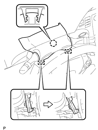
REMOVE LOWER STEERING COLUMN COVER
Note
Removing the lower steering column cover in the incorrect order will cause the lower steering column cover to break.
-
Release the tilt and telescopic lever, and fully extend and lower the steering column assembly.
-
Lock the tilt and telescopic lever.
-
Push the right and left sides of the lower steering column cover to disengage the 4 claws.
-
Insert fingers into the opening of the tilt lever of the lower steering column cover to disengage the claw.
Tech Tips
Spread the claw to disengage it.
-
Text in Illustration *1 Protective Tape Turn the steering wheel assembly to the right.
-
Using a screwdriver, disengage the claw as shown in the illustration.
Tech Tips
Tape the screwdriver tip before use.
-
Text in Illustration *1 Protective Tape Turn the steering wheel assembly to the left.
-
Using a screwdriver, disengage the claw as shown in the illustration.
Tech Tips
Tape the screwdriver tip before use.
-
Remove the lower steering column cover as shown in the illustration.
-
-
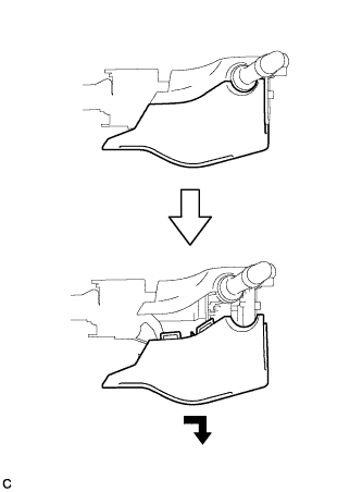
REMOVE UPPER STEERING COLUMN COVER
-
Disengage the claw and 2 pins, and remove the upper steering column cover.
-
-
REMOVE TURN SIGNAL SWITCH ASSEMBLY WITH SPIRAL CABLE SUB-ASSEMBLY
-
Disconnect the connectors from the turn signal switch assembly with spiral cable sub-assembly.
-
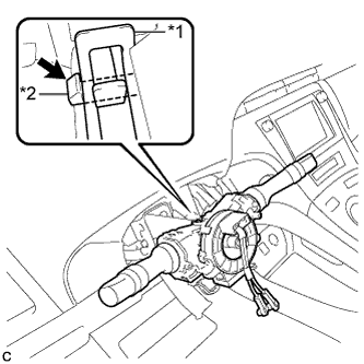
Text in Illustration *1 Clamp *2 Claw Using pliers, expand the clamp.
-
While holding the clamp expanded, raise the claw using a screwdriver to disengage it, and then remove the turn signal switch assembly with spiral cable sub-assembly from the steering column assembly.
-
-
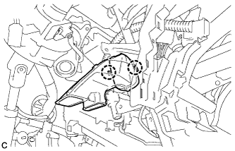
REMOVE NO. 1 INSTRUMENT PANEL UNDER COVER SUB-ASSEMBLY (for LHD)
-
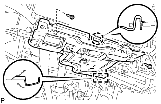
Remove the 2 screws <D>.
-
Disengage the claw and guide.
-
Disconnect each connector and remove the No. 1 instrument panel under cover sub-assembly.
-
-
REMOVE NO. 1 INSTRUMENT PANEL UNDER COVER SUB-ASSEMBLY (for RHD)
-
Remove the screw <D>.
-
Disengage the 2 claws and guide.
-
Disconnect each connector and remove the No. 1 instrument panel under cover sub-assembly.
-
-
REMOVE DRIVER SIDE KNEE AIRBAG ASSEMBLY
CAUTION:
When storing the driver side knee airbag assembly, keep the airbag deployment side facing upward.
-
Check that the power switch is off.
-
Check that the cable is disconnected from the negative (-) battery terminal.
CAUTION:
Wait at least 90 seconds after disconnecting the cable from the negative (-) battery terminal to disable the SRS system.
-
Remove the 4 bolts.
-
Disengage the 2 claws to separate the DLC3.
-
Disengage the 6 claws and 4 guides to separate the driver side knee airbag assembly.
-
Disengage the clamp to separate the wire harness.
-
Using a screwdriver with the tip wrapped with protective tape, release the airbag connector lock.
Text in Illustration *1 Protective Tape -
Disconnect the airbag connector to remove the driver side knee airbag assembly.
Note
When disconnecting any airbag connector, take care not to damage the airbag wire harness.
-
-
REMOVE NO. 2 INSTRUMENT PANEL UNDER COVER SUB-ASSEMBLY
-
Disengage the 3 claws and guide.
-
Disconnect each connector and remove the No. 2 instrument panel under cover sub-assembly.
-
-
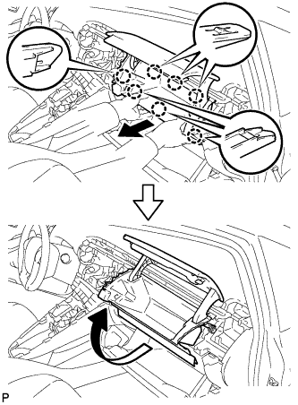
REMOVE GLOVE COMPARTMENT DOOR ASSEMBLY
-
for LHD:
-
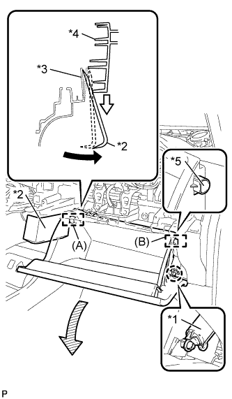
Text in Illustration *1 Glove Compartment Door Stopper Sub-assembly *2 Moulding Remover *3 Lower Instrument Panel Sub-assembly *4 Glove Compartment Door Assembly *5 Stopper Disengage the claw and release the glove compartment door stopper.
-
Insert the moulding remover into the location shown in the illustration.
-
Move the moulding remover in the direction indicated by the arrow to bend the lower instrument panel sub-assembly and release the stopper (A).
Tech Tips
Use the same procedure to release the stopper (B).
-
-
for RHD:
-
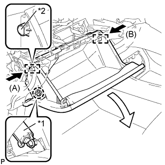
Text in Illustration *1 Glove Compartment Door Stopper Sub-assembly *2 Stopper Disengage the claw and release the glove compartment door stopper.
-
Slightly bend stoppers (A) and (B) in the directions indicated by the arrows in the illustration and pull the glove compartment door assembly until the stoppers are released.
-
-
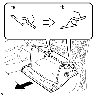
Text in Illustration *a Close *b Open Approximately Open the glove compartment door assembly to approximately 55° from its closed position. Pull it horizontally in the direction indicated by the arrow to disengage the 2 hinges and remove the glove compartment door assembly.
Note
Pulling the glove compartment door assembly upward to remove it causes the hinges to deform. Be sure to pull out the glove compartment door assembly horizontally.
-
-
REMOVE FRONT DOOR SCUFF PLATE RH
Tech Tips
Use the same procedure for the RH side and LH side.
-
REMOVE COWL SIDE TRIM BOARD RH
Tech Tips
Use the same procedure for the RH side and LH side.
-
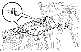
REMOVE NO. 1 HEATER TO REGISTER DUCT
-
Remove the 3 clips and the No. 1 heater to register duct.
-
-
REMOVE COMBINATION METER ASSEMBLY
-
Disconnect the 3 connectors.
-
Disengage the clamp.
-
Remove the 3 screws.
-
Disengage the clip and remove the combination meter assembly.
-
-
REMOVE POWER STEERING ECU ASSEMBLY
-
Text in Illustration *1 Lock of the Lock Lever *2 Lock Lever Disengage the wire harness clamp from the power steering ECU assembly.
-
Disconnect the connector from the power steering ECU assembly.
Tech Tips
As shown in the illustration, pull out the lock of the lock lever and turn the lock lever to disconnect the connector.
-
Disconnect the 3 connectors from the power steering ECU assembly.
-
Remove the bolt, 2 nuts, and the power steering ECU assembly.
-
-
REMOVE NO. 2 ANTENNA CORD SUB-ASSEMBLY (for LHD)
-
for Plug Type Antenna Cord:
-
Disconnect the 2 connectors.
-
Remove the bolt.
-
Disengage the 4 clamps and remove the No. 2 antenna cord sub-assembly.
-
-
for Connector Type Antenna Cord:
-
Disconnect the connector.
-
Remove the bolt.
-
Disengage the 4 clamps and remove the No. 2 antenna cord sub-assembly.
-
-
w/ Digital Audio Broadcasting Antenna:
-
Disconnect the 2connectors.
-
Remove the bolt.
-
Disengage the 5 clamps and remove the No. 2 antenna cord sub-assembly.
-
-
-
REMOVE NO. 2 ANTENNA CORD SUB-ASSEMBLY (for RHD)
-
for Plug Type Antenna Cord:
-
Disconnect the 2 connectors.
-
Remove the bolt.
-
Disengage the 5 clamps and remove the No. 2 antenna cord sub-assembly.
-
-
for Connector Type Antenna Cord:
-
Disconnect the connector.
-
Remove the bolt.
-
Disengage the 5 clamps and remove the No. 2 antenna cord sub-assembly.
-
-
w/ Digital Audio Broadcasting Antenna:
-
Disconnect the 2connectors.
-
Remove the bolt.
-
Disengage the 6 clamps and remove the No. 2 antenna cord sub-assembly.
-
-
-
REMOVE LOWER INSTRUMENT PANEL SUB-ASSEMBLY (for LHD)
-
Disengage each clamp.
-
Remove the 4 bolts <B>, 11 bolts <C> and screw <D> and lower instrument panel sub-assembly.
Text in Illustration *1 Bolt <B> *2 Bolt <C> *3 Screw <D> - -
-
-
REMOVE LOWER INSTRUMENT PANEL SUB-ASSEMBLY (for RHD)
-
Disengage the 2 claws.
-
Disengage each clamp.
-
Remove the 4 bolts <B>, 11 bolts <C> and screw <D> and lower instrument panel sub-assembly.
Text in Illustration *1 Bolt <B> *2 Bolt <C> *3 Screw <D> - -
-
-
REMOVE HEADUP DISPLAY
-
Disconnect the connector.
-
Disengage the clamp.
-
Remove the bolt, 2 nuts and headup display.
-
-
REMOVE ECU INTEGRATION BOX LH (for RHD)
-
Disconnect each connector.
-
Disengage the clamp and disconnect the wire harness.
-
Remove the bolt, nut and ECU integration box.
-
-
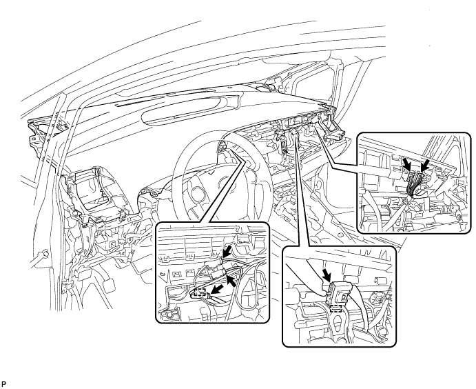
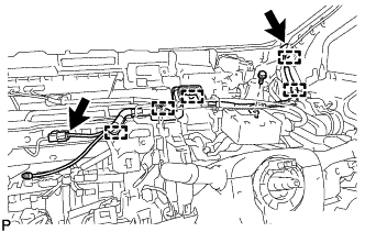
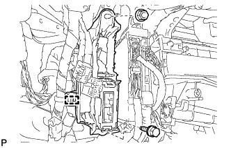
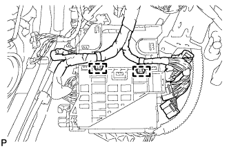
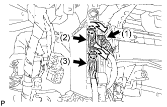
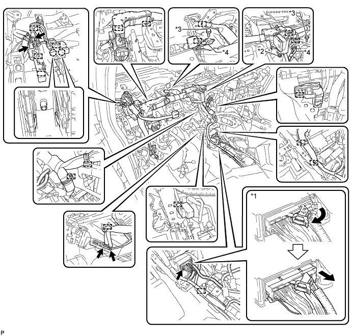
REMOVE DRIVER SIDE JUNCTION BLOCK ASSEMBLY (for LHD)
-
Disengage the clamp and disconnect the wire harness.
-
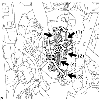
Disconnect the 3 connectors (1), (2) and (3).
-
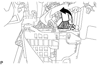
Disengage the 2 claws and disconnect the 2 connectors (4) and (5) as shown in the illustration.
-
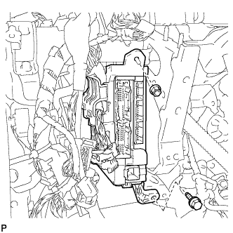
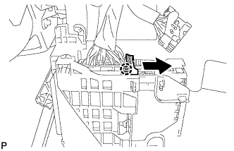
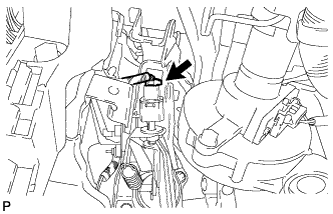
Remove the bolt and nut, and disconnect the driver side junction block assembly.
-
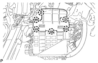
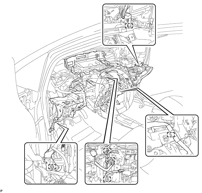
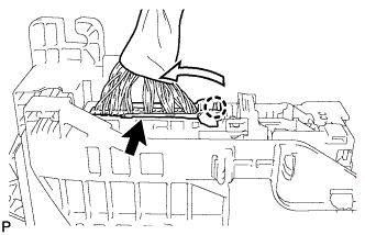
Disengage the 6 claws and remove the junction block bracket.
-
Disengage the 2 clamps and disconnect the wire harness.
-
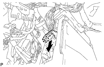
Disengage the claw and disconnect the connector as shown in the illustration.
-
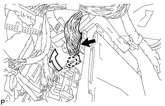
Disengage the claw and release the connector lock as shown in the illustration.
-
Disengage the claw and disconnect the connector as shown in the illustration.
-
Remove the driver side junction block assembly.
-
-
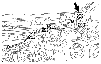
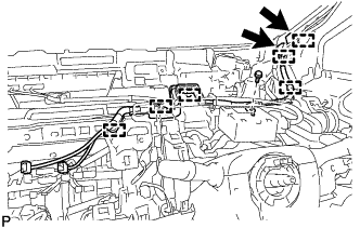
REMOVE FRONT PASSENGER SIDE JUNCTION BLOCK ASSEMBLY (for RHD)
-
Disconnect the connector (1).
-
Disengage the 2 claws and disconnect the connector (2) and (3) as shown in the illustration.
-

Disengage the 2 clamps and disconnect the wire harness.
-
Remove the bolt and nut, and disconnect the front passenger side junction block assembly.
-

Disengage the clamp and disconnect the wire harness.
-
Disengage the claw and disconnect the connector as shown in the illustration.
-
Disengage the claw and release the connector lock as shown in the illustration.
-
Disengage the claw and disconnect the connector as shown in the illustration.
-
Remove the front passenger side junction block assembly.
-
-
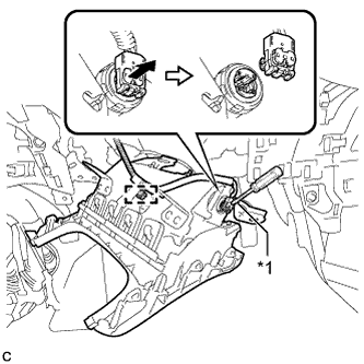
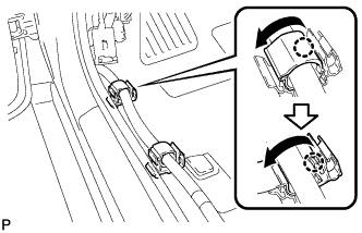
REMOVE STOP LIGHT SWITCH ASSEMBLY
-
Disconnect the connector.
-
Turn the stop light switch assembly counterclockwise and remove it.
-
-
REMOVE STOP LIGHT SWITCH MOUNTING ADJUSTER
-
REMOVE BRAKE PEDAL RETURN SPRING
for LHD: Click here
for RHD: Click here
-
REMOVE PUSH ROD PIN
for LHD: Click here
for RHD: Click here
-
REMOVE BRAKE PEDAL SUPPORT ASSEMBLY
for LHD: Click here
for RHD: Click here
-
REMOVE NO. 2 AIR DUCT SUB-ASSEMBLY
-
Disengage the 2 claws to remove the No. 2 air duct sub-assembly.
-
-
REMOVE COLUMN HOLE COVER SILENCER SHEET
-
Turn back the floor carpet.
-
Remove the 2 clips and column hole cover silencer sheet.
-
-
SEPARATE NO. 2 STEERING INTERMEDIATE SHAFT ASSEMBLY
-
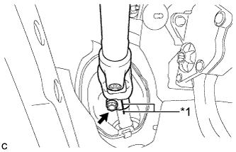
Text in Illustration *1 Matchmark Put matchmarks on the No. 2 steering intermediate shaft assembly and steering intermediate shaft.
Note
Do not separate the No. 2 steering intermediate shaft assembly from the steering intermediate shaft.
-
Remove the bolt.
-
Separate the No. 2 steering intermediate shaft assembly from the steering intermediate shaft.
-
-
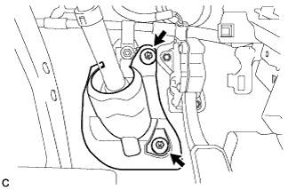
REMOVE STEERING POST ASSEMBLY
-
Disengage the 2 wire harness clamps.
-
Disconnect the connector from the power steering ECU assembly.
Tech Tips
As shown in the illustration, turn the lock lever to disconnect the connector.
-
Disconnect the connector from the power steering ECU assembly.
-
Disconnect the connectors and disengage the wire harness clamps from the steering post assembly.
-
Remove the bolt, 2 nuts and steering post assembly.
-
-
REMOVE REAR NO. 2 AIR DUCT
-
Disengage each claw to open the 2 door scuff plate clamps as shown in the illustration.
-
Disengage the clip and fastener.
-
Disengage the 2 claws and turn back the floor carpet as shown in the illustration.
Text in Illustration *1 Fastener -
Disengage the 2 claws and remove the rear No. 2 air duct.
-
-
REMOVE REAR NO. 3 AIR DUCT
-
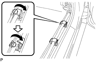
Disengage each claw to open the 2 door scuff plate clamps as shown in the illustration.
-
Disengage the clip and fastener.
-
Disengage the 2 claws and turn back the floor carpet as shown in the illustration.
Text in Illustration *1 Fastener -
Disengage the 2 claws and remove the rear No. 3 air duct.
-
-
REMOVE REAR NO. 1 AIR DUCT
-
Disengage the 4 claws and remove the rear No. 1 air duct.
-
-
REMOVE NO. 3 SIDE DEFROSTER NOZZLE DUCT
-
Remove the clip and No. 3 side defroster nozzle duct.
-
-
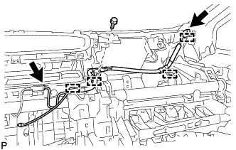
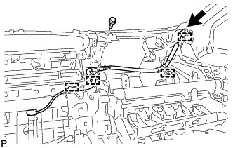
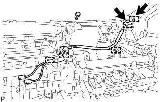
REMOVE NO. 1 INSTRUMENT PANEL BRACE SUB-ASSEMBLY
-
Check that the power switch is off.
-
Check that the cable is disconnected from the negative (-) battery terminal.
CAUTION:
Wait at least 90 seconds after disconnecting the cable from the negative (-) battery terminal to disable the SRS system.
-
Disconnect the center airbag sensor connectors from the center airbag sensor assembly as shown in the illustration.
Note
When disconnecting any airbag connector, take care not to damage the airbag wire harness.
-
Remove the screw.
-
Remove the 2 bolts and disconnect the 2 earth wires.
-
Disconnect each connector.
-
Disengage each clamp and claw.
Text in Illustration *1 Center airbag sensor connector *2 Screw *3 Bolt *4 Earth wires -
Remove the screw.
-
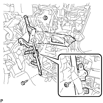
Remove the bolt, nut and No. 1 instrument panel brace sub-assembly.
-
-
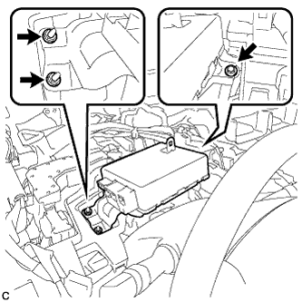
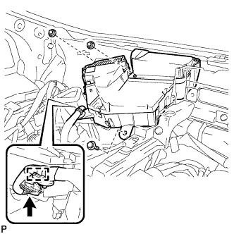
REMOVE NO. 2 INSTRUMENT PANEL BRACE SUB-ASSEMBLY
-
Remove the 3 screws <A>.
-
Remove the bolt and disconnect the earth wire.
-
Disconnect each connector.
-
Disengage each clamp.
-
Remove the screw <B> and 2 nuts from the computer integration box RH.
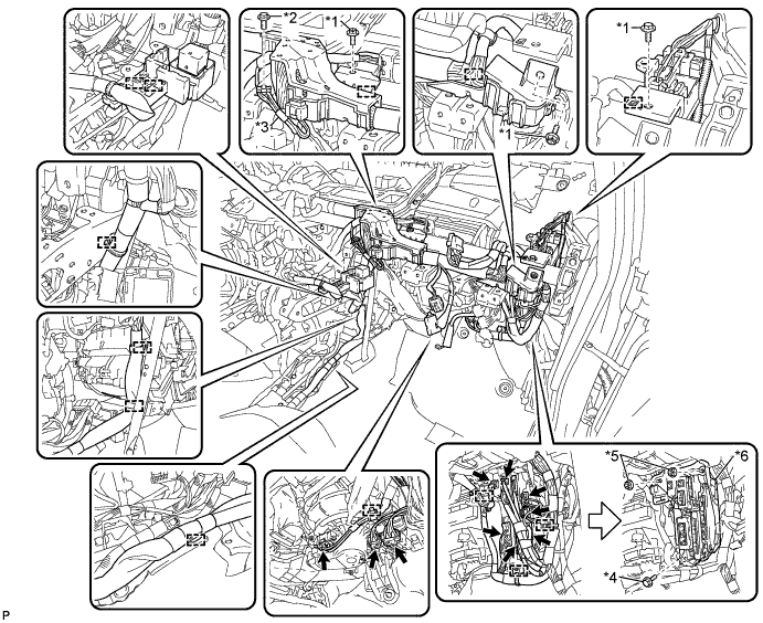
Text in Illustration *1 Screw <A> *2 Bolt *3 Earth wires *4 Screw <B> *5 Nut *6 Computer integration box RH -
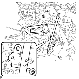
Remove the screw.
-
Remove the bolt, nut and No. 2 instrument panel brace sub-assembly.
-
-
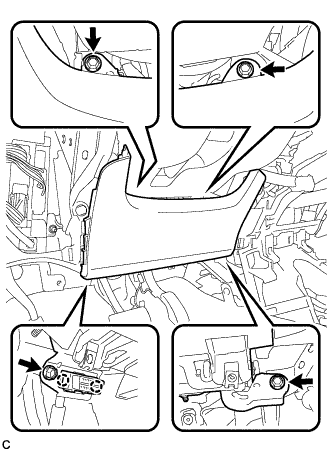
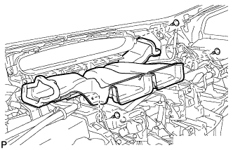
REMOVE DEFROSTER NOZZLE ASSEMBLY
-
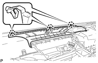
Disengage the 3 claws.
-
Remove the defroster nozzle assembly as shown in the illustration.
-
-
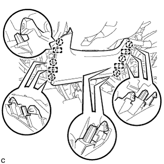
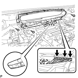
REMOVE LOWER DEFROSTER NOZZLE ASSEMBLY
-
Disengage the clamp.
-
Disengage the 6 claws and remove the lower defroster nozzle assembly.
-
-
REMOVE NO. 3 AIR DUCT SUB-ASSEMBLY
-
Remove the 2 nuts and No. 3 air duct sub-assembly.
-
-
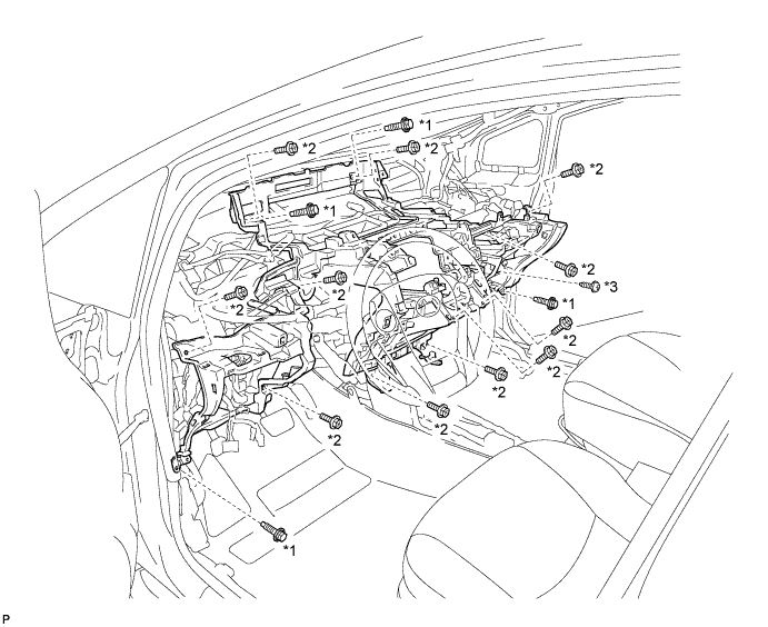
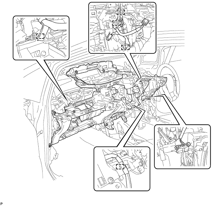
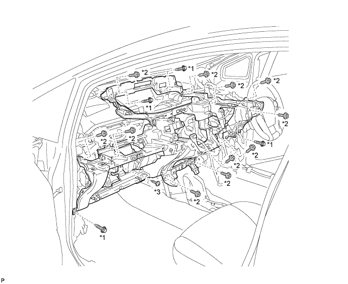
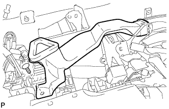
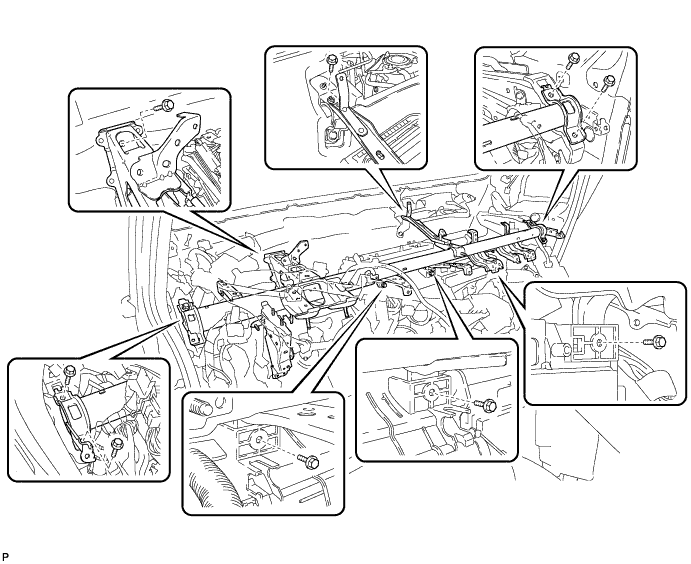
REMOVE INSTRUMENT PANEL REINFORCEMENT ASSEMBLY
-
Disengage each clamp.
-
Remove the 9 bolts and instrument panel reinforcement assembly.
-
-
REMOVE AIR CONDITIONING UNIT ASSEMBLY
Note
-
Be sure to support the air conditioning unit assembly when removing it because failure to do so may cause the bracket of the air conditioning unit assembly to break.
-
When disassembling the air conditioning unit, eliminate static electricity by touching the vehicle body to prevent the components from being damaged.
-
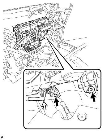
Disengage the cooler drain hose.
-
Remove the bolt, nut and air conditioning unit assembly.
-