SOLAR VENTILATION SYSTEM Solar Ventilation ECU Power Source Circuit
DESCRIPTION
For the solar ventilation system, the moon roof glass assembly (solar panel) generates electricity using sunlight to generate the required power.
The electricity generated by the moon roof glass assembly (solar panel) is sent to the solar ventilation ECU and used as the power source for the solar ventilation system.
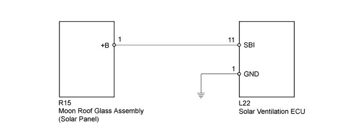
WIRING DIAGRAM
INSPECTION PROCEDURE
PROCEDURE
-
INSPECT MOON ROOF GLASS ASSEMBLY (SOLAR PANEL)
-
Leave the vehicle for 10 minutes in a location where the following conditions are met, and then measure the voltage.
System Operation Requirements Items Condition Amount of sunlight A sufficient amount of sunlight is received by the moon roof glass assembly (solar panel).
(The amount of sunlight on a cloudless day between 11:00 and 14:00 is typically sufficient for operation.)
Moon roof glass assembly (solar panel) status The moon roof glass assembly (solar panel) is not in the shade No fallen leaves or dirt is present on the moon roof glass assembly (solar panel) Ambient temperature 20 to 40°C (68 to 104°F) Note
To ensure stable generation of voltage by the moon roof glass assembly (solar panel), make sure to park the vehicle in a location where the system operation requirements are satisfied.
-
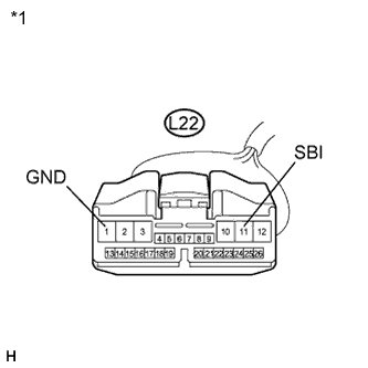
Text in Illustration *1 Front view of wire harness connector
(to Solar Ventilation ECU)
Disconnect the solar ventilation ECU connector.
CAUTION:
The moon roof glass assembly (solar panel) generates electricity when exposed to a light source such as sunlight. If an inspection of the moon roof glass assembly (solar panel) is performed while electricity is being generated, work carefully in order to prevent an accidental short circuit or electric shock.
-
Measure the voltage according to the value(s) in the table below.
Standard Voltage Tester Connection Condition Specified Condition L22-11 (SBI) - L22-1 (GND) System operation requirements are met. 12 V or higher
NG 
CHECK HARNESS AND CONNECTOR (SOLAR VENTILATION ECU - SOLAR PANEL, BODY GROUND) Click here
OK 
-
-
READ VALUE USING INTELLIGENT TESTER
-
Reconnect the solar ventilation ECU connector.
-
Connect the intelligent tester to the DLC3.
-
Turn the power switch on (IG).
-
Turn the intelligent tester on.
-
Enter the following menus: Body / Air Conditioner / Data List.
-
Check the value(s) by referring to the table below.
-
Check that the Solar Voltage value in the Data List is 10 V or higher.
Air Conditioner Tester Display Measurement Item/Range Normal Condition Diagnostic Note Solar Voltage Solar panel voltage /
10V les, 10V-11V, 11V-12V, 12V-13V, 13V-14V, 14V-15V, 15V-16V, 16V-17V, 17V-18V, 18V-19V, 19V-20V, 20V-21V, 21V-22V, 22V-23V or 23V ovr
Actual generated voltage displayed System operation requirements are met Click here.
OK 10 V or higher Tech Tips
If the Data List items are not displayed, inspect the communication circuit between the solar ventilation ECU and A/C amplifier Click here.
-
NG 
REPLACE SOLAR VENTILATION ECU Click here
OK 
PROCEED TO NEXT SUSPECTED AREA SHOWN IN PROBLEM SYMPTOMS TABLE Click here
-
-
CHECK HARNESS AND CONNECTOR (SOLAR VENTILATION ECU - SOLAR PANEL, BODY GROUND)
-
Disconnect the solar ventilation ECU connector.
-
Disconnect the moon roof glass assembly (solar panel) connector.
-
Measure the resistance according to the value(s) in the table below.
Standard Resistance Tester Connection Condition Specified Condition L22-11 (SBI) - R15-1 (+B) Always Below 1 Ω L22-1 (GND) - Body ground Always Below 1 Ω L22-11 (SBI) - Body ground Always 10 kΩ or higher Text in Illustration *1 Front view of wire harness connector
(to Solar Ventilation ECU)
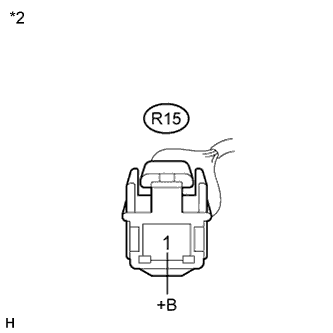
*2 Front view of wire harness connector
(to Moon Roof Glass Assembly (Solar Panel))
NG
REPAIR OR REPLACE HARNESS OR CONNECTOR
OK
REPLACE MOON ROOF GLASS ASSEMBLY (SOLAR PANEL) Click here
-