SOLAR VENTILATION SYSTEM Solar Ventilation Switch Circuit
DESCRIPTION
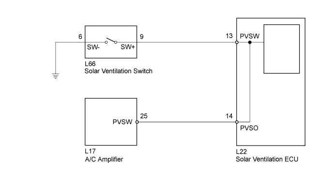
The solar ventilation system can operate when the solar ventilation switch is on and the moon roof glass assembly (solar panel) generates the necessary amount of electricity.
WIRING DIAGRAM
INSPECTION PROCEDURE
Tech Tips
Before performing this inspection procedure, check if the Data List items for the solar ventilation system are displayed. If the Data List items are not displayed, inspect the communication circuit between the solar ventilation ECU and A/C amplifier Click here.
PROCEDURE
-
READ VALUE USING INTELLIGENT TESTER
-
Connect the intelligent tester to the DLC3.
-
Turn the power switch on (IG).
-
Turn the intelligent tester on.
-
Enter the following menus: Body / Air Conditioner / Data List.
-
Check the value(s) by referring to the table below.
Air Conditioner Tester Display Measurement Item/Range Normal Condition Diagnostic Note Solar Ventilation Switch Solar ventilation switch (Switch recognition value at A/C amplifier side) / OFF or ON OFF: Solar ventilation switch off
ON: Solar ventilation switch on
- Solar Ventilation Switch Status Solar ventilation switch (Switch recognition value at solar ventilation ECU side) / OFF or ON OFF: Solar ventilation switch off
ON: Solar ventilation switch on
- OK The display is as specified in the Normal Condition column. Result Result Proceed to OK A NG
(OFF/ON display does not change for both Solar Ventilation Switch Status and Solar Ventilation Switch even though the solar ventilation switch is operated.)
B NG
(OFF/ON display does not change for Solar Ventilation Switch even though the solar ventilation switch is operated.)
C NG
(OFF/ON display does not change for Solar Ventilation Switch Status even though the solar ventilation switch is operated.)
D
B 
INSPECT SOLAR VENTILATION SWITCH Click here
C
CHECK HARNESS AND CONNECTOR (SOLAR VENTILATION ECU - A/C AMPLIFIER) Click here
D 
REPLACE SOLAR VENTILATION ECU Click here
A 
PROCEED TO NEXT SUSPECTED AREA SHOWN IN PROBLEM SYMPTOMS TABLE Click here
-
-
INSPECT SOLAR VENTILATION SWITCH
-
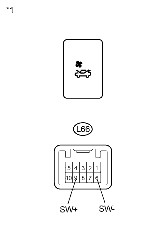
Text in Illustration *1 Component without harness connected
(Solar Ventilation Switch)
Remove the solar ventilation switch.
-
Measure the resistance according to the value(s) in the table below.
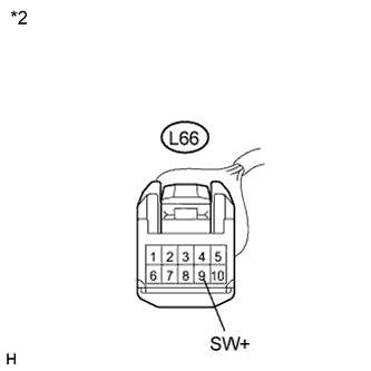
Standard Resistance Tester Connection Condition Specified Condition L66-9 (SW+) - L66-6 (SW-) Solar ventilation switch: off
(when switch is not pressed)
10 kΩ or higher L66-9 (SW+) - L66-6 (SW-) Solar ventilation switch: on
when switch pressed)
Below 1 Ω
NG
REPLACE SOLAR VENTILATION SWITCH Click here
OK 
-
-
CHECK HARNESS AND CONNECTOR (SOLAR VENTILATION SWITCH - BODY GROUND)
-
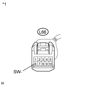
Text in Illustration *1 Front view of wire harness connector
(to Solar Ventilation Switch)
Measure the resistance according to the value(s) in the table below.
Standard Resistance Tester Connection Condition Specified Condition L66-6 (SW-) - Body ground Always Below 1 Ω
NG
REPAIR OR REPLACE HARNESS OR CONNECTOR
OK
-
-
CHECK HARNESS AND CONNECTOR (SOLAR VENTILATION SWITCH - SOLAR VENTILATION ECU)
-
Disconnect the solar ventilation ECU connector.
-
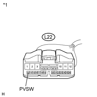
Text in Illustration *1 Front view of wire harness connector
(to Solar Ventilation ECU)
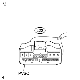
*2 Front view of wire harness connector
(to Solar Ventilation Switch)
Measure the resistance according to the value(s) in the table below.
Standard Resistance Tester Connection Condition Specified Condition L22-13 (PVSW) - L66-9 (SW+) Always Below 1 Ω L22-13 (PVSW) - Body ground Always 10 kΩ or higher
NG
REPAIR OR REPLACE HARNESS OR CONNECTOR
OK
REPLACE SOLAR VENTILATION ECU Click here
-
-
CHECK HARNESS AND CONNECTOR (SOLAR VENTILATION ECU - A/C AMPLIFIER)
-
Disconnect the A/C amplifier connector.
-
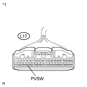
Text in Illustration *1 Front view of wire harness connector
(to A/C Amplifier)
*2 Front view of wire harness connector
(to Solar Ventilation ECU)
Measure the resistance according to the value(s) in the table below.
Standard Resistance Tester Connection Condition Specified Condition L17-25 (PVSW) - L22-14 (PVSO) Always Below 1 Ω L17-25 (PVSW) - Body ground Always 10 kΩ or higher
NG
REPAIR OR REPLACE HARNESS OR CONNECTOR
OK
-
-
REPLACE SOLAR VENTILATION ECU
-
Replace the solar ventilation ECU with a known good one and check if the same problem occurs again Click here.
OK Same problem does not occur.
NG
REPLACE A/C AMPLIFIER Click here
OK
END (SOLAR VENTILATION ECU WAS DEFECTIVE)
-