SOLAR VENTILATION SYSTEM Blower Motor Circuit
DESCRIPTION
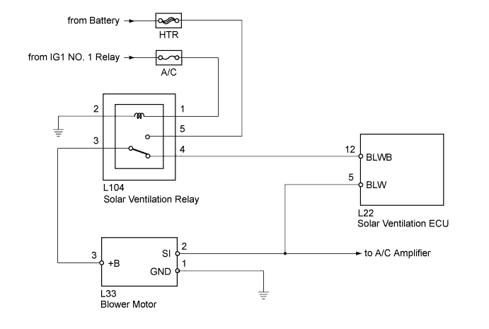
The solar ventilation system and air conditioning system use the same blower motor for ventilation.
In order to be driven by each system, the blower motor switches between two different power sources using the solar ventilation relay. When the power switch is off, power from the solar ventilation system is supplied to the blower motor and when the power switch is in a mode other than off, power from the air conditioning system is supplied to the blower motor.
The blower motor controls its operation and speed using the power and signals supplied by the solar ventilation ECU when the power switch is off.
Changes its speed according to the amount of sunlight received by the moon roof glass assembly (solar panel).
WIRING DIAGRAM
INSPECTION PROCEDURE
Note
Inspect the fuses for circuits related to this system before performing the following inspection procedure.
PROCEDURE
-
PERFORM ACTIVE TEST USING INTELLIGENT TESTER
-
Connect the intelligent tester to the DLC3.
-
Turn the power switch on (IG).
-
Turn the intelligent tester on.
-
Enter the following menus: Body / Air Conditioner / Active Test.
-
Check the operation by referring to the table below.
Air Conditioner Tester Display Test Part Control Range Diagnostic Note Blower Motor Blower motor Min.: 0, Max.: 31 - OK Blower motor operates and blower motor speed level changes.
NG 
GO TO AIR CONDITIONING SYSTEM (BLOWER MOTOR CIRCUIT) Click here
OK 
-
-
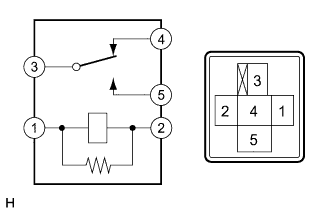
INSPECT SOLAR VENTILATION RELAY
-
Remove the solar ventilation relay.
-
Measure the resistance according to the value(s) in the table below.
Standard Resistance Tester Connection Specified Condition 3 - 5 10 kΩ or higher 3 - 4 Below 1 Ω 3 - 5 Below 1 Ω
(when battery voltage is applied to terminals 1 and 2)
3 - 4 10 kΩ or higher
(when battery voltage is applied to terminals 1 and 2)
NG
REPLACE SOLAR VENTILATION RELAY
OK
-
-
INSPECT SOLAR VENTILATION ECU
-
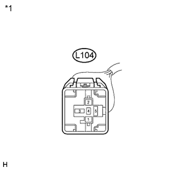
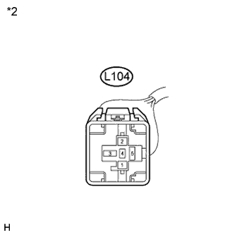
Text in Illustration *1 Front view of wire harness connector
(to Solar Ventilation Relay)
Disconnect the solar ventilation relay connector.
-
Measure the voltage according to the value(s) in the table below.
Standard Voltage Tester Connection Condition Specified Condition L104-4 - Body ground Power switch off
Solar ventilation switch off
Below 1 V L104-4 - Body ground Power switch off
Solar ventilation switch on
(System operation requirements met Click here
1 to 28 V
NG 
CHECK HARNESS AND CONNECTOR (SOLAR VENTILATION ECU - SOLAR VENTILATION RELAY) Click here
OK
-
-
CHECK HARNESS AND CONNECTOR (SOLAR VENTILATION ECU - BLOWER MOTOR)
-
Disconnect the solar ventilation ECU connector.
-
Disconnect the blower motor connector.
-
Measure the resistance according to the value(s) in the table below.
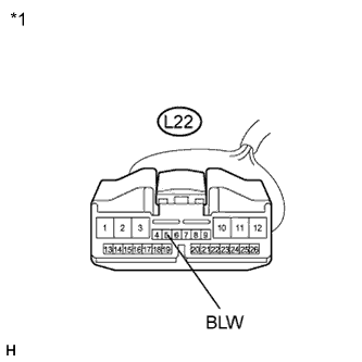
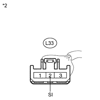
Standard Resistance Tester Connection Condition Specified Condition L22-5 (BLW) - L33-2 (SI) Always Below 1 Ω L22-5 (BLW) - Body ground Always 10 kΩ or higher Text in Illustration *1 Front view of wire harness connector
(to Solar Ventilation ECU)
*2 Front view of wire harness connector
(to Blower Motor)
NG
REPAIR OR REPLACE HARNESS OR CONNECTOR
OK
-
-
INSPECT SOLAR VENTILATION ECU
-
Reinstall the solar ventilation relay.
-
Reconnect the solar ventilation relay connector.
-
Reconnect the blower motor connector.
-
Reconnect the solar ventilation ECU connector.
-
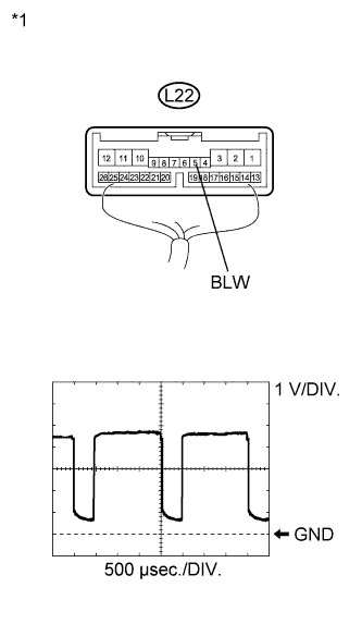
Text in Illustration *1 Component with harness connected
(Solar Ventilation ECU)
Measure the waveform between terminal L22-5 (BLW) of the solar ventilation ECU and body ground.
Item Content Tool setting 1 V/DIV., 500 μs/DIV. Vehicle condition Power switch off
Solar ventilation switch on (blower motor operating)
OK Waveform is as shown in the illustration. Tech Tips
The waveform varies with the blower speed.
NG
REPLACE BLOWER MOTOR Click here
OK 
PROCEED TO NEXT SUSPECTED AREA SHOWN IN PROBLEM SYMPTOMS TABLE Click here
-
-
REPLACE BLOWER MOTOR
-
Replace the blower motor with a known good one and check if the same problem occurs again Click here.
OK Same problem does not occur.
NG
REPLACE SOLAR VENTILATION ECU Click here
OK
END (BLOWER MOTOR WAS DEFECTIVE)
-
-
CHECK HARNESS AND CONNECTOR (SOLAR VENTILATION ECU - SOLAR VENTILATION RELAY)
-
Disconnect the solar ventilation ECU connector.
-
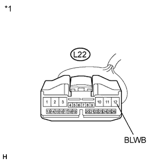
Text in Illustration *1 Front view of wire harness connector
(to Solar Ventilation ECU)
*2 Front view of wire harness connector
(to Solar Ventilation Relay)
Measure the resistance according to the value(s) in the table below.
Standard Resistance Tester Connection Condition Specified Condition L22-12 (BLWB) - L104-4 Always Below 1 Ω L22-12 (BLWB) - Body ground Always 10 kΩ or higher
NG
REPAIR OR REPLACE HARNESS OR CONNECTOR
OK
REPLACE SOLAR VENTILATION ECU Click here
-