COMPRESSOR INSTALLATION

-
ADJUST COMPRESSOR OIL
-
When replacing the electric inverter compressor with a new one, gradually discharge the refrigerant gas from the service valve, and drain the following amount of oil from the new electric inverter compressor before installation.
Standard (Oil capacity inside the new electric inverter compressor: 130 to 145 cc (4.4 to 4.9 fl. oz.)) - (Remaining oil amount in the removed electric inverter compressor) = (Oil amount to be removed from the new compressor when replacing) Note
-
When checking the compressor oil level, observe the precautions on the cooler removal/installation.
-
If a new compressor and magnetic clutch are installed without removing some oil, there will be too much oil in the system due to the oil remaining in the pipes of the vehicle. Excessive oil in the system prevents heat exchange in the refrigeration cycle and causes refrigeration failure.
-
If the amount of oil remaining in the old compressor and magnetic clutch is too small, check the A/C system for oil leaks.
-
Be sure to use ND-OIL 11 or equivalent for compressor oil. If any compressor oil other than ND-OIL 11 is used, compressor motor insulation performance may decrease, resulting in a leakage of electric power.
-
-
-
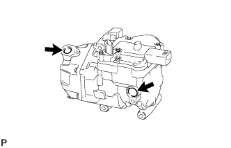
INSTALL ELECTRIC INVERTER COMPRESSOR
-
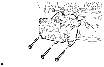
Temporarily install the electric inverter compressor with the 3 bolts.
-
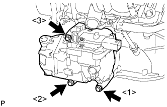
Install the electric inverter compressor with the 3 bolts.
- Torque:
- 25 N*m { 250 kgf*cm, 18 ft.*lbf }
Note
Tighten the bolts in the order shown in the illustration to install the electric inverter compressor.
-
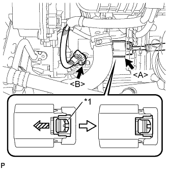
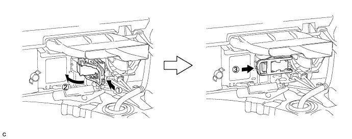
Text in Illustration *1 Green-colored Lock Connect the connector <B>.
-
Connect the connector <A> and slide the green-colored lock in the direction indicated by the arrow in the illustration to lock it securely.
CAUTION:
Make sure to wear insulating gloves.
Note
Make sure that the connector is connected securely.
-
-
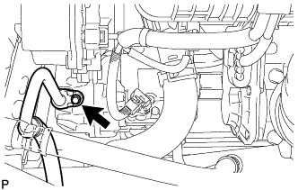
CONNECT SUCTION HOSE SUB-ASSEMBLY
-
Remove the attached vinyl tape from the hose.
-
Sufficiently apply compressor oil to a new O-ring and the fitting surface of the compressor and magnetic clutch.
Compressor oil ND-OIL 11 or equivalent -
Install the O-ring onto the suction hose sub-assembly.
Note
-
Keep the O-ring and O-ring fitting surfaces free from dirt or any foreign objects.
-
Do not use any compressor oil other than ND-OIL 11 or equivalent. If any compressor oil other than ND-OIL 11 or equivalent is used, compressor motor insulation performance may decrease, resulting in a leakage of electric power.
-
-
Install the suction hose sub-assembly onto the compressor and magnetic clutch with the bolt.
- Torque:
- 9.8 N*m { 100 kgf*cm, 87 in.*lbf }
-
-
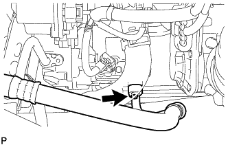
CONNECT DISCHARGE HOSE SUB-ASSEMBLY
-
Remove the attached vinyl tape from the hose.
-
Sufficiently apply compressor oil to a new O-ring and the fitting surface of the compressor and magnetic clutch.
Compressor oil ND-OIL 11 or equivalent -
Install the O-ring onto the discharge hose sub-assembly.
Note
-
Keep the O-ring and O-ring fitting surfaces free from dirt or any foreign objects.
-
Do not use any compressor oil other than ND-OIL 11 or equivalent. If any compressor oil other than ND-OIL 11 or equivalent is used, compressor motor insulation performance may decrease, resulting in a leakage of electric power.
-
-
Install the discharge hose sub-assembly onto the compressor and magnetic clutch with the bolt.
- Torque:
- 9.8 N*m { 100 kgf*cm, 87 in.*lbf }
-
-
INSTALL SERVICE PLUG GRIP
CAUTION:
Wear insulating gloves.
Note
Before connecting the service plug, check that no parts and tools remain and that the high voltage terminals and connectors are connected securely.
-
Wear insulated gloves and install the service plug grip in the order shown in the illustration.
-
Rotate the handle of the service plug grip 90° toward the battery and slide it in the direction shown by the arrow until a click sound is heard.
-
-
CONNECT CABLE TO NEGATIVE BATTERY TERMINAL
Note
When disconnecting the cable, some systems need to be initialized after the cable is reconnected Click here.
-
INSTALL REAR NO. 3 FLOOR BOARD
-

Engage the 2 guides to install the rear No. 3 floor board.
-
-
INSTALL REAR DECK FLOOR BOX
-
Install the rear deck floor box.
-
-
INSTALL REAR NO. 2 FLOOR BOARD
-

Engage the 3 guides <A>.
-
Engage the 2 guides <B> and install the rear No. 2 floor board as shown in the illustration.
-
-
CHARGE WITH REFRIGERANT
-
Perform vacuum purging using a vacuum pump.
-
Charge with refrigerant HFC-134a (R134a).
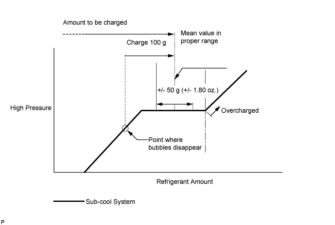
Standard 470 g (16.6 oz.) - SST
- 09985-20010 ( 09985-02010, 09985-02050, 09985-02060, 09985-02070, 09985-02080, 09985-02090, 09985-02110, 09985-02130, 09985-02140, 09985-02150 )
Note
-
Do not turn the A/C on before charging with refrigerant. Doing so will cause the compressor to work without refrigerant, resulting in overheating of the cooler compressor.
-
Approximately 100 g (3.53 oz.) of refrigerant may need to be charged after bubbles disappear. The refrigerant amount should be checked by quantity, not with the sight glass.
-
Avoid using the gauge manifold set that had been used for vehicles with conventional compressor oil (ND-OIL 8 or equivalent) as much as possible. This will cause compressor oil remaining in the manifold to enter the vehicle, resulting in insulation performance deterioration. A gauge manifold set that had been used 3 times or less can be reused if an appropriate one is not available.
Tech Tips
Ensure that sufficient refrigerant is available to recharge the system when using a refrigerant recovery unit. Refrigerant recovery units are not always able to recover 100% of the refrigerant from an A/C system.
-
-
WARM UP COMPRESSOR
-
Keep the A/C switch on for at least 2 minutes to warm up the compressor.
Note
Be sure to warm up the compressor when turning the A/C on after removing and installing the cooler refrigerant lines (including the compressor), to prevent damage to the compressor.
-
-
INSPECT FOR REFRIGERANT LEAK
-
After recharging with refrigerant, inspect for refrigerant leaks using a halogen leak detector.
-
Carry out the test under the following conditions:
-
Turn the power switch off.
-
Secure good ventilation (the halogen leak detector may react to volatile gases which are not refrigerant, such as evaporated gasoline and exhaust gas).
-
Repeat the test 2 or 3 times.
-
Make sure that there is some refrigerant remaining in the refrigeration system.
When the compressor is off: approx. 392 to 588 kPa (3.9 to 5.9 kgf/cm2, 57 to 85 psi)
-
-
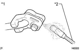
Text in Illustration *1 Inspect for Leak *2 Halogen Leak Detector Using a halogen leak detector, inspect for refrigerant leaks from the refrigerant lines.
-
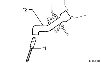
Text in Illustration *1 Halogen Leak Detector *2 Drain Hose Bring the halogen leak detector close to the drain hose with the detector's power off, and then turn the detector on.
Tech Tips
-
After the blower motor has stopped, let the cooling unit stand for more than 15 minutes.
-
Bring the halogen leak detector sensor under the drain hose.
-
When bringing the halogen leak detector close to the drain hose, make sure that the halogen leak detector does not react to volatile gases. If it is not possible to avoid interference from volatile gases, the vehicle should be lifted up to allow testing.
-
-
If a refrigerant leak is not detected from the drain hose, remove the blower motor control from the cooling unit. Insert the halogen leak detector sensor into the unit and perform the test.
-
Disconnect the pressure switch connector and leave it for approximately 20 minutes. Bring the halogen leak detector close to the pressure switch and perform the test.
-
-
INSTALL NO. 1 ENGINE UNDER COVER
-
INSTALL FRONT SPOILER COVER (w/ Front Spoiler)
-
INSTALL INLET AIR CLEANER ASSEMBLY
-
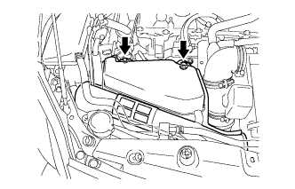
Install the inlet air cleaner assembly with the 2 bolts.
- Torque:
- 7.0 N*m { 71 kgf*cm, 62 in.*lbf }
-