AIR CONDITIONING SYSTEM PTC Heater Circuit
DESCRIPTION
The PTC heater assembly is installed in the radiator in the heater unit and operates when engine coolant temperature is low and normal heater effectiveness is insufficient.
The A/C control assembly switches the circuit in the PTC relay and operates the PTC heater assembly when the operating conditions (cooling water temperature is below 65°C (149°F), setting temperature is MAX. HOT, ambient temperature is below 10°C (50°F) and blower switch is not OFF) are met.
The PTC heater assembly controls PTC heater lines by electric load or the amount of inverter with converter assembly (PCU) output. Therefore, troubleshooting should be performed with other electric components off.
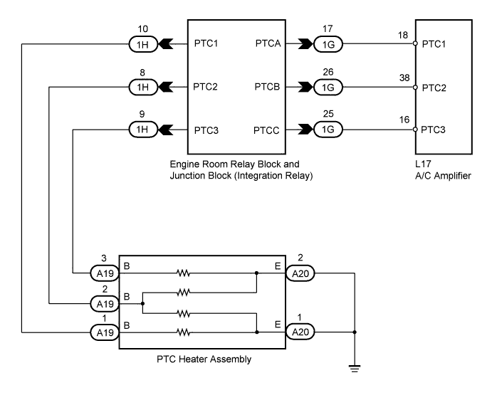
WIRING DIAGRAM
INSPECTION PROCEDURE
PROCEDURE
-
INSPECT PTC HEATER ASSEMBLY
-
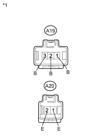
Text in Illustration *1 Component without harness connected
(PTC Heater Assembly)
Remove the PTC heater assembly.
-
Measure the resistance according to the value(s) in the table below.
Standard Resistance Tester Connection Condition Specified Condition A19-1 (B) - A20-1 (E) Always Below 1 Ω A19-2 (B) - A20-2 (E) Always Below 1 Ω A19-2 (B) - A20-1 (E) Always Below 1 Ω A19-3 (B) - A20-2 (E) Always Below 1 Ω
NG 
REPLACE PTC HEATER ASSEMBLY Click here
OK 
-
-
CHECK HARNESS AND CONNECTOR (PTC HEATER ASSEMBLY - BODY GROUND)
-
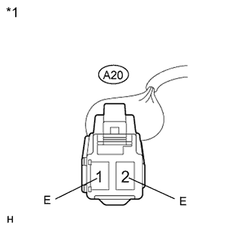
Text in Illustration *1 Front view of wire harness connector
(to PTC Heater Assembly)
Measure the resistance according to the value(s) in the table below.
Standard Resistance Tester Connection Condition Specified Condition A20-1 (E) - Body ground Always Below 1 Ω A20-2 (E) - Body ground Always Below 1 Ω
NG
REPAIR OR REPLACE HARNESS OR CONNECTOR
OK
-
-
CHECK HARNESS AND CONNECTOR (PTC HEATER ASSEMBLY - INTEGRATION RELAY)
-
Disconnect the PTC heater assembly connector.
-
Disconnect the engine room relay block and junction block (integration relay) connector.
-
Measure the resistance according to the value(s) in the table below.
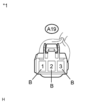
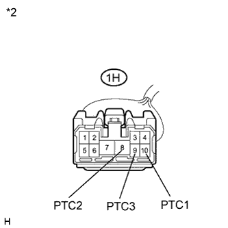
Standard Resistance Tester Connection Condition Specified Condition A19-1 (B) - 1H-10 (PTC1) Always Below 1 Ω A19-2 (B) - 1H-8 (PTC2) Always Below 1 Ω A19-3 (B) - 1H-9 (PTC3) Always Below 1 Ω A19-1 (B) - Body ground Always 10 kΩ or higher A19-2 (B) - Body ground Always 10 kΩ or higher A19-3 (B) - Body ground Always 10 kΩ or higher Text in Illustration *1 Front view of wire harness connector
(to PTC Heater Assembly)
*2 Front view of wire harness connector
(to Engine Room Relay Block and Junction Block (Integration Relay))
NG
REPAIR OR REPLACE HARNESS OR CONNECTOR
OK
-
-
CHECK HARNESS AND CONNECTOR (A/C AMPLIFIER - INTEGRATION RELAY)
-
Disconnect the A/C amplifier connector.
-
Disconnect the engine room relay block and junction block (integration relay) connector.
-
Measure the resistance according to the value(s) in the table below.
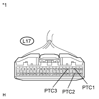
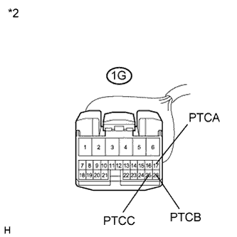
Standard Resistance Tester Connection Condition Specified Condition L17-18 (PTC1) - 1G-17 (PTCA) Always Below 1 Ω L17-38 (PTC2) - 1G-26 (PTCB) Always Below 1 Ω L17-16 (PTC3) - 1G-25 (PTCC) Always Below 1 Ω L17-18 (PTC1) - Body ground Always 10 kΩ or higher L17-38 (PTC2) - Body ground Always 10 kΩ or higher L17-16 (PTC3) - Body ground Always 10 kΩ or higher Text in Illustration *1 Front view of wire harness connector
(to A/C Amplifier)
*2 Front view of wire harness connector
(to Engine Room Relay Block and Junction Block (Integration Relay))
NG
REPAIR OR REPLACE HARNESS OR CONNECTOR
OK
-
-
REPLACE INTEGRATION NO.1 RELAY
-
Replace the integration relay Click here.
Tech Tips
Since the integration relay cannot be inspected while it is removed from the vehicle, replace the integration relay with a new or a known good one and check that the condition returns to normal.
-
Check if the same problem occurs again.
OK Same problem does not occur.
NG
PROCEED TO NEXT SUSPECTED AREA SHOWN IN PROBLEM SYMPTOMS TABLE Click here
OK 
END (INTEGRATION RELAY WAS DEFECTIVE)
-