SOLAR VENTILATION SYSTEM IG Signal Circuit
DESCRIPTION
The solar ventilation system activates when the vehicle power switch is off. If the solar ventilation switch has been turned on, the solar ventilation ECU checks that the vehicle power switch is off and then activates the solar ventilation system.
WIRING DIAGRAM
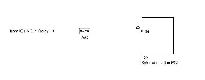
INSPECTION PROCEDURE
Note
Inspect the fuses for circuits related to this system before performing the following inspection procedure.
Tech Tips
Before performing this inspection procedure, check if the Data List items for the solar ventilation system are displayed. If the Data List items are not displayed, inspect the communication circuit between the solar ventilation ECU and A/C amplifier Click here.
PROCEDURE
-
READ VALUE USING INTELLIGENT TESTER
-
Connect the intelligent tester to the DLC3.
-
Turn the power switch on (IG).
-
Turn the intelligent tester on.
-
Enter the following menus: Body / Air Conditioner / Data List.
-
Check the value(s) by referring to the table below.
Air Conditioner Tester Display Measurement Item/Range Normal Condition Diagnostic Note Solar IG Status Solar ventilation ECU IG status / OFF or ON OFF: Power switch off
ON: Power switch on (IG)
When OFF is displayed, a malfunction in the solar ventilation ECU is suspected. OK The display is as specified in the Normal Condition column. Result Result Proceed to NG A OK
(When troubleshooting according to Problem Symptoms Table (for Solar Ventilation System))
B OK
(When troubleshooting according to Problem Symptoms Table (for Air Conditioning System))
C
B 
PROCEED TO NEXT SUSPECTED AREA SHOWN IN PROBLEM SYMPTOMS TABLE Click here
C
PROCEED TO NEXT SUSPECTED AREA SHOWN IN PROBLEM SYMPTOMS TABLE Click here
A 
-
-
CHECK HARNESS AND CONNECTOR (SOLAR VENTILATION ECU - BATTERY)
-
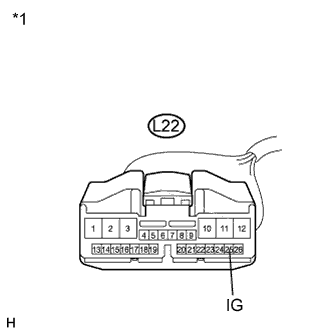
Text in Illustration *1 Front view of wire harness connector
(to Solar Ventilation ECU)
Disconnect the solar ventilation ECU connector.
-
Measure the voltage according to the value(s) in the table below.
Standard Voltage Tester Connection Condition Specified Condition L22-25 (IG) - Body ground Power switch off Below 1 V L22-25 (IG) - Body ground Power switch on (IG) 11 to 14 V
NG
REPAIR OR REPLACE HARNESS OR CONNECTOR
OK 
REPLACE SOLAR VENTILATION ECU Click here
-