AIR CONDITIONING SYSTEM Blower Motor Circuit
DESCRIPTION
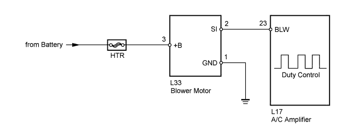
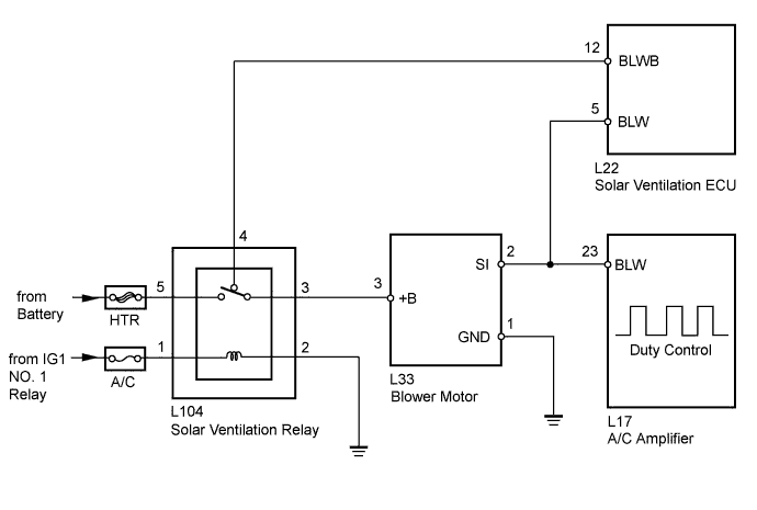
The blower motor is operated by signals from the A/C amplifier. Blower motor speed signals are transmitted in accordance with changes in the duty ratio.
WIRING DIAGRAM
-
w/o Solar Ventilation System
-
w/ Solar Ventilation System
INSPECTION PROCEDURE
Note
Inspect the fuses for circuits related to this system before performing the following inspection procedure.
PROCEDURE
-
PERFORM ACTIVE TEST USING INTELLIGENT TESTER
-
Connect the intelligent tester to the DLC3.
-
Turn the power switch on (IG).
-
Turn the intelligent tester on.
-
Enter the following menus: Body / Air Conditioner / Active Test.
-
Check the operation by referring to the table below.
Air Conditioner Tester Display Test Part Control Range Diagnostic Note Blower Motor Blower motor Min.: 0, Max.: 31 - OK Blower motor operates and blower motor speed level changes. Result Result Proceed to OK A NG (Blower motor does not operate)
(w/o Solar ventilation system)
B NG (Blower motor does not operate)
(w/ Solar ventilation system)
C NG (Blower motor operates but does not change speed)
(w/o Solar ventilation system)
D NG (Blower motor operates but does not change speed)
(w/ Solar ventilation system)
E
B 
CHECK HARNESS AND CONNECTOR (BLOWER MOTOR - BODY GROUND) Click here
C
INSPECT SOLAR VENTILATION RELAY Click here
D
INSPECT A/C AMPLIFIER Click here
E
CHECK HARNESS AND CONNECTOR (BLOWER MOTOR - A/C AMPLIFIER) Click here
A 
PROCEED TO NEXT SUSPECTED AREA SHOWN IN PROBLEM SYMPTOMS TABLE Click here
-
-
CHECK HARNESS AND CONNECTOR (BLOWER MOTOR - BODY GROUND)
-
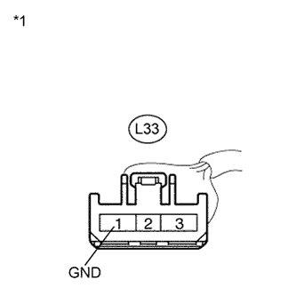
Text in Illustration *1 Front view of wire harness connector
(to Blower Motor)
Disconnect the blower motor connector.
-
Measure the resistance according to the value(s) in the table below.
Standard Resistance Tester Connection Condition Specified Condition L33-1 (GND) - Body ground Always Below 1 Ω
NG 
REPAIR OR REPLACE HARNESS OR CONNECTOR
OK 
-
-
CHECK HARNESS AND CONNECTOR (BLOWER MOTOR - BATTERY)
-
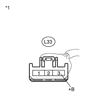
Text in Illustration *1 Front view of wire harness connector
(to Blower Motor)
Measure the voltage according to the value(s) in the table below.
Standard Voltage Tester Connection Condition Specified Condition L33-3 (+B) - Body ground Power switch off 11 to 14 V
NG
REPAIR OR REPLACE HARNESS OR CONNECTOR
OK
-
-
CHECK HARNESS AND CONNECTOR (BLOWER MOTOR - A/C AMPLIFIER)
-
Disconnect the A/C amplifier connector.
-
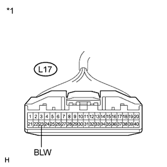
Text in Illustration *1 Front view of wire harness connector
(to A/C Amplifier)
*2 Front view of wire harness connector
(to Blower Motor)
Measure the resistance according to the value(s) in the table below.
Standard Resistance Tester Connection Condition Specified Condition L17-23 (BLW) - L33-2 (SI) Always Below 1 Ω L17-23 (BLW) - Body ground Always 10 kΩ or higher
NG
REPAIR OR REPLACE HARNESS OR CONNECTOR
OK
-
-
INSPECT BLOWER MOTOR
-
Reconnect the blower motor connector.
-

Text in Illustration *1 Front view of wire harness connector
(to A/C Amplifier)
Measure the voltage according to the value(s) in the table below.
Standard Voltage Tester Connection Condition Specified Condition L17-23 (BLW) - Body ground Power switch off 4.5 to 5.5 V
NG
REPLACE BLOWER MOTOR Click here
OK
-
-
INSPECT A/C AMPLIFIER
-
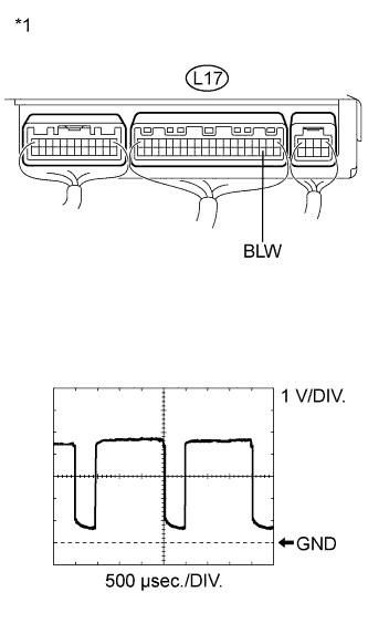
Text in Illustration *1 Component with harness connected
(A/C Amplifier)
Remove the A/C amplifier.
-
Reconnect the A/C amplifier connector.
-
Turn the power switch on (IG).
-
Set the blower speed to LO.
-
Measure the waveform between terminal L17-23 (BLW) of the A/C amplifier and body ground.
Item Content Tool setting 1 V/DIV., 500 μs/DIV. Vehicle condition Power switch on (IG)
Blower set to LO
OK Waveform is as shown in the illustration. Tech Tips
The waveform varies with the blower speed.
NG
REPLACE A/C AMPLIFIER Click here
OK
REPLACE BLOWER MOTOR Click here
-
-
INSPECT SOLAR VENTILATION RELAY
-
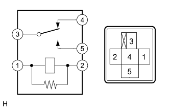
Remove the solar ventilation relay from the relay block No. 2-1.
-
Measure the resistance according to the value(s) in the table below.
Standard Resistance Tester Connection Specified Condition 3 - 5 10 kΩ or higher 3 - 4 Below 1 Ω 3 - 5 Below 1 Ω
(when battery voltage is applied to terminals 1 and 2)
3 - 4 10 kΩ or higher
(when battery voltage is applied to terminals 1 and 2)
NG
REPLACE SOLAR VENTILATION RELAY
OK
-
-
CHECK HARNESS AND CONNECTOR (RELAY BLOCK NO. 2-1 - BATTERY)
-
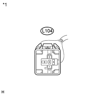
Text in Illustration *1 Front view of wire harness connector
(to Relay Block No. 2-1)
Disconnect the relay block No. 2-1 connector.
-
Measure the voltage according to the value(s) in the table below.
Standard Voltage Tester Connection Condition Specified Condition L104-1 - Body ground Power switch off or on (ACC) Below 1 V L104-1 - Body ground Power switch on (IG) 11 to 14 V L104-5 - Body ground Always 11 to 14 V
NG
REPAIR OR REPLACE HARNESS OR CONNECTOR
OK
-
-
CHECK HARNESS AND CONNECTOR (RELAY BLOCK NO. 2-1 - BODY GROUND)
-
Text in Illustration *1 Front view of wire harness connector
(to Relay Block No. 2-1)
Measure the resistance according to the value(s) in the table below.
Standard Resistance Tester Connection Condition Specified Condition L104-2 - Body ground Always Below 1 Ω
NG
REPAIR OR REPLACE HARNESS OR CONNECTOR
OK
-
-
CHECK HARNESS AND CONNECTOR (BLOWER MOTOR - BODY GROUND)
-
Text in Illustration *1 Front view of wire harness connector
(to Blower Motor)
Disconnect the blower motor connector.
-
Measure the resistance according to the value(s) in the table below.
Standard Resistance Tester Connection Condition Specified Condition L33-1 (GND) - Body ground Always Below 1 Ω
NG
REPAIR OR REPLACE HARNESS OR CONNECTOR
OK
-
-
CHECK HARNESS AND CONNECTOR (BLOWER MOTOR - BATTERY)
-
Reinstall the solar ventilation relay to the relay block No. 2-1.
-
Text in Illustration *1 Front view of wire harness connector
(to Blower Motor)
Measure the voltage according to the value(s) in the table below.
Standard Voltage Tester Connection Condition Specified Condition L33-3 (+B) - Body ground Power switch off or on (ACC) Below 1 V L33-3 (+B) - Body ground Power switch on (IG) 11 to 14 V
NG
REPAIR OR REPLACE HARNESS OR CONNECTOR (BLOWER MOTOR - RELAY BLOCK NO. 2-1)
OK
-
-
CHECK HARNESS AND CONNECTOR (BLOWER MOTOR - A/C AMPLIFIER)
-
Disconnect the A/C amplifier connector.
-
Disconnect the solar ventilation ECU connector.
-
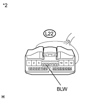
Text in Illustration *1 Front view of wire harness connector
(to A/C Amplifier)
*2 Front view of wire harness connector
(to Solar Ventilation ECU)
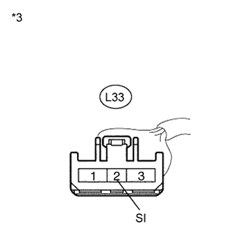
*3 Front view of wire harness connector
(to Blower Motor)
Measure the resistance according to the value(s) in the table below.
Standard Resistance Tester Connection Condition Specified Condition L17-23 (BLW) - L33-2 (SI) Always Below 1 Ω L17-23 (BLW) - Body ground Always 10 kΩ or higher
NG
REPAIR OR REPLACE HARNESS OR CONNECTOR
OK
-
-
INSPECT BLOWER MOTOR
-
Reconnect the blower motor connector.
-
Text in Illustration *1 Front view of wire harness connector
(to A/C Amplifier)
Measure the voltage according to the value(s) in the table below.
Standard Voltage Tester Connection Condition Specified Condition L17-23 (BLW) - Body ground Power switch off or on (ACC) Below 1 V L17-23 (BLW) - Body ground Power switch on (IG) 4.5 to 5.5 V
NG
REPLACE BLOWER MOTOR Click here
OK
-
-
INSPECT A/C AMPLIFIER
-
Text in Illustration *1 Component with harness connected
(A/C Amplifier)
Remove the A/C amplifier.
-
Reconnect the A/C amplifier connector.
-
Turn the power switch on (IG).
-
Set the blower speed to LO.
-
Measure the waveform between terminal L17-23 (BLW) of the A/C amplifier and body ground.
Item Content Tool setting 1 V/DIV., 500 μs/DIV. Vehicle condition Power switch on (IG)
Blower set to LO
OK Waveform is as shown in the illustration. Tech Tips
The waveform varies with the blower speed.
NG
REPLACE A/C AMPLIFIER Click here
OK
REPLACE BLOWER MOTOR Click here
-