SOLAR VENTILATION SYSTEM OPERATION CHECK

-
SOLAR VENTILATION SYSTEM OPERATION CHECK
-
Inspection of Voltage Generated by Moon Roof Glass Assembly (Solar Panel)
-
Park the vehicle in a location with a stable temperature and a sufficient amount of sunlight, and leave the vehicle as is for approximately 10 minutes.
Note
To ensure stable generation of voltage by the moon roof glass assembly (solar panel), make sure to park the vehicle in a location where the system operation requirements are satisfied.
Tech Tips
The solar ventilation system operates only when the generated voltage is 10 V or higher. Therefore, make sure to park the vehicle where the system operation requirements are satisfied. This will allow the moon roof glass assembly (solar panel) to generate a voltage of 10 V or higher.
System Operation Requirements Item Condition Amount of sunlight A sufficient amount of sunlight is received by the moon roof glass assembly (solar panel).
(The amount of sunlight on a cloudless day between 11:00 and 14:00 is typically sufficient for operation.)
Moon roof glass assembly (solar panel) status The moon roof glass assembly (solar panel) is not in the shade No fallen leaves or dirt is present on the moon roof glass assembly (solar panel) Ambient temperature 20 to 40°C (68 to 104°F) -
Connect the intelligent tester to the DLC3.
-
Turn the power switch on (IG).
-
Turn the intelligent tester on.
-
Enter the following menus: Body / Air Conditioner / Data List.
Air Conditioner Tester Display Measurement Item/Range Normal Condition Diagnostic Note Solar Voltage Solar panel voltage /
10V les, 10V-11V, 11V-12V, 12V-13V, 13V-14V, 14V-15V, 15V-16V, 16V-17V, 17V-18V, 18V-19V, 19V-20V, 20V-21V, 21V-22V, 22V-23V or 23V ovr
Actual generated voltage displayed System operation requirements are met Click here.
Tech Tips
If the Data List items related to the solar ventilation system are not displayed, the following conditions are suspected:
-
The voltage generated by the moon roof glass assembly (solar panel) is less than 7 V Click here.
-
There is a communication error between the solar ventilation ECU and A/C amplifier Click here.
-
-
-
Operation Check
-
Check that the Solar Voltage value in the Data List is 10 V or higher.
-
Turn the solar ventilation switch on.
-
Turn the power switch off.
-
Check that the blower motor operates 10 minutes after the power switch is turned off.
Tech Tips
-
The inlets will be changed to fresh air mode and the outlets will be changed to face mode approximately 1 minute after the power switch is turned off.
-
Inlet and outlet modes will remain unchanged when the solar ventilation switch is turned on after the power switch is turned off.
-
When the moon roof glass assembly (solar panel) is generating high voltage, a noise may occur when the blower motor starts operating. This noise does not indicate a malfunction.
-
For details of the solar ventilation system control, refer to System Description Click here.
-
-
-
-
TEST MODE
Tech Tips
In test mode, the solar ventilation ECU operates the blower motor while the power switch is on (IG). The state of the solar ventilation switch received by the solar ventilation ECU and the status of duty output from the solar ventilation ECU to the blower motor can be checked.
-
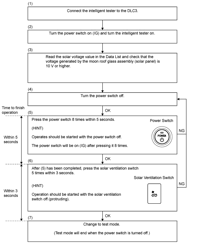
Test Mode Procedure
-
Check that the Solar Voltage value in the Data List is 10 V or higher.
-
Press the power switch 8 times within 5 seconds.
Tech Tips
Operates should be started with power switch off.
-
Press the solar ventilation switch 5 times within 3 seconds.
Tech Tips
Operation should be started with the solar ventilation switch off (protruding).
-
Check that test mode is activated and the blower motor rotates at a constant speed.
Tech Tips
-
When the solar ventilation switch is turned off, the blower motor will stop and when the solar ventilation switch is turned on, the blower motor will operate.
-
When the power switch is turned off, the solar ventilation system returns to normal control.
-
-
-