PRE-CRASH SAFETY SYSTEM Power Source Circuit
DESCRIPTION
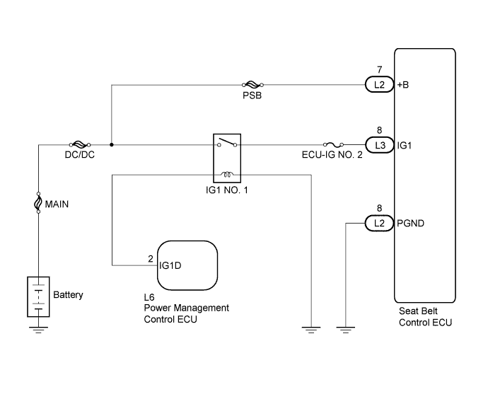
This circuit supplies power to the seat belt control ECU.
WIRING DIAGRAM
INSPECTION PROCEDURE
Note
Inspect the fuses for circuits related to this system before performing the following inspection procedure.
PROCEDURE
-
CHECK HARNESS AND CONNECTOR (PGND CIRCUIT)
-
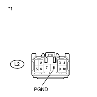
Text in Illustration *1 Front view of wire harness connector
(to Seat Belt Control ECU)
Disconnect the seat belt control ECU connector.
-
Measure the resistance according to the value(s) in the table below.
Standard Resistance Tester Connection Condition Specified Condition L2-8 (PGND) - Body ground Always Below 1 Ω -
Reconnect the seat belt control ECU connector.
NG 
REPAIR OR REPLACE HARNESS OR CONNECTOR (PGND CIRCUIT)
OK 
-
-
CHECK HARNESS AND CONNECTOR (IG1 CIRCUIT)
-
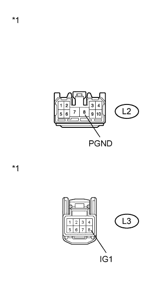
Text in Illustration *1 Front view of wire harness connector
(to Seat Belt Control ECU)
Disconnect the seat belt control ECU connector.
-
Turn the power switch on (IG).
-
Measure the voltage according to the value(s) in the table below.
Standard Voltage Tester Connection Condition Specified Condition L3-8 (IG1) - L2-8 (PGND) Power switch on (IG) 11 to 14 V -
Reconnect the seat belt control ECU connector.
NG 
INSPECT INSTRUMENT PANEL JUNCTION BLOCK ASSEMBLY Click here
OK
-
-
CHECK HARNESS AND CONNECTOR (+B CIRCUIT)
-
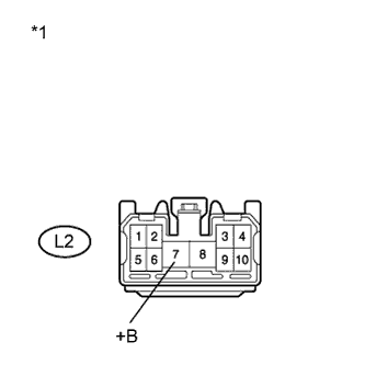
Text in Illustration *1 Front view of wire harness connector
(to Seat Belt Control ECU)
Disconnect the seat belt control ECU connector.
-
Measure the voltage according to the value(s) in the table below.
Standard Voltage Tester Connection Condition Specified Condition L2-7 (+B) - Body ground Always 11 to 14 V -
Reconnect the seat belt control ECU connector.
NG
REPAIR OR REPLACE HARNESS OR CONNECTOR (+B CIRCUIT)
OK 
PROCEED TO NEXT SUSPECTED AREA SHOWN IN PROBLEM SYMPTOMS TABLE Click here
-
-
INSPECT INSTRUMENT PANEL JUNCTION BLOCK ASSEMBLY
-
Remove the instrument panel junction block assembly.
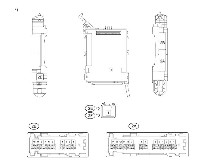
Text in Illustration *1 Instrument Panel Junction Block Assembly *2 LHD *3 RHD - - -
Measure the resistance according to the value(s) in the table below.
Standard Resistance for LHD Tester Connection Condition Specified Condition 2E-1 - 2B-16 Always 10 kΩ or higher 2E-1 - 2B-16 When battery voltage applied to terminals 2B-25 and 2B-6 Below 1 Ω for RHD Tester Connection Condition Specified Condition 2F-1 - 2B-16 Always 10 kΩ or higher 2F-1 - 2B-16 When battery voltage applied to terminals 2B-25 and 2B-6 Below 1 Ω -
Reinstall the instrument panel junction block assembly.
NG
REPLACE INSTRUMENT PANEL JUNCTION BLOCK ASSEMBLY
OK
-
-
CHECK HARNESS AND CONNECTOR (INSTRUMENT PANEL JUNCTION BLOCK - SEAT BELT CONTROL ECU)
-
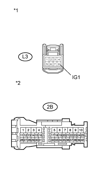
Text in Illustration *1 Front view of wire harness connector
(to Seat Belt Control ECU)
*2 Front view of wire harness connector
(to Instrument Panel Junction Block Assembly)
Disconnect the instrument panel junction block assembly connector.
-
Disconnect the seat belt control ECU connector.
-
Measure the resistance according to the value(s) in the table below.
Standard Resistance Tester Connection Condition Specified Condition 2B-16 - L3-8 (IG1) Always Below 1 Ω 2B-16 - Body ground Always 10 kΩ or higher L3-8 (IG1) - Body ground Always 10 kΩ or higher -
Reconnect the seat belt control ECU connector.
-
Reconnect the instrument panel junction block assembly connector.
NG
REPAIR OR REPLACE HARNESS OR CONNECTOR (INSTRUMENT PANEL JUNCTION BLOCK - SEAT BELT CONTROL ECU)
OK
-
-
CHECK HARNESS AND CONNECTOR (INSTRUMENT PANEL JUNCTION BLOCK - BODY GROUND)
-
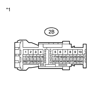
Text in Illustration *1 Front view of wire harness connector
(to Instrument Panel Junction Block Assembly)
Disconnect the instrument panel junction block assembly connector.
-
Measure the resistance according to the value(s) in the table below.
Standard Resistance Tester Connection Condition Specified Condition 2B-6 - Body ground Always Below 1 Ω -
Reconnect the instrument panel junction block assembly connector.
NG
REPAIR OR REPLACE HARNESS OR CONNECTOR (INSTRUMENT PANEL JUNCTION BLOCK - BODY GROUND)
OK
-
-
CHECK HARNESS AND CONNECTOR (INSTRUMENT PANEL J/B - POWER MANAGEMENT CONTROL ECU)
-
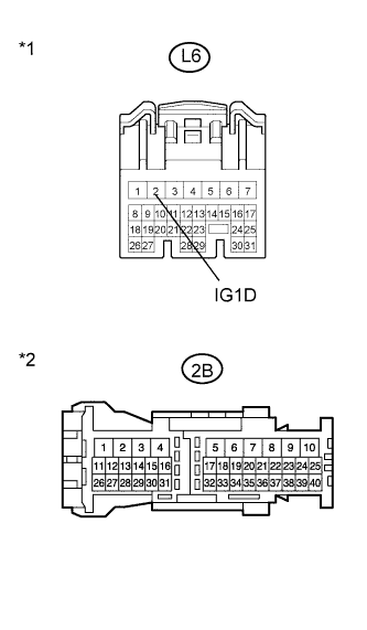
Text in Illustration *1 Front view of wire harness connector
(to Power Management control ECU)
*2 Front view of wire harness connector
(to Instrument Panel Junction Block Assembly)
Disconnect the instrument panel junction block assembly connector.
-
Disconnect the power management control ECU connector.
-
Measure the resistance according to the value(s) in the table below.
Standard Resistance Tester Connection Condition Specified Condition 2B-25 - L6-2 (IG1D) Always Below 1 Ω 2B-25 - Body ground Always 10 kΩ or higher L6-2 (IG1D) - Body ground Always 10 kΩ or higher -
Reconnect the power management control ECU connector.
-
Reconnect the instrument panel junction block assembly connector.
NG
REPAIR OR REPLACE HARNESS OR CONNECTOR (INSTRUMENT PANEL J/B - POWER MANAGEMENT CONTROL ECU)
OK
REPAIR OR REPLACE HARNESS OR CONNECTOR (INSTRUMENT PANEL JUNCTION BLOCK - BATTERY)
-