PRE-CRASH SAFETY SYSTEM, Diagnostic DTC:B2005

| DTC Code | DTC Name |
|---|---|
| B2005 | Short to B+ in Seat Belt Motor LH Circuit |
DESCRIPTION
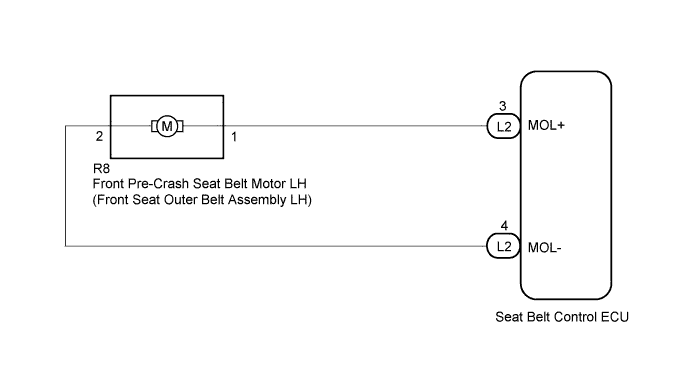
The seat belt control ECU receives information from the driving support ECU using CAN communication and tightens the seat belt by operating the motor in the front seat outer belt assembly LH.
| DTC No. | DTC Detection Condition | Trouble Area |
|---|---|---|
| B2005 | Short to B+ in the seat belt motor LH circuit continues for 1 second or more. |
|
WIRING DIAGRAM
INSPECTION PROCEDURE
CAUTION:
The pretensioner is built into the front seat outer belt assembly LH. Be sure to follow the correct inspection procedure, as failure to follow the correct procedure (such as inspection of incorrect connectors) may deploy the pretensioner.
PROCEDURE
-
INSPECT FRONT SEAT OUTER BELT ASSEMBLY LH
-
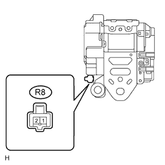
Disconnect the front seat outer belt assembly LH connector.
-
Turn the power switch on (IG).
-
Measure the voltage according to the value(s) in the table below.
Standard Voltage Tester Connection Switch Condition Specified Condition R8-1 - Body ground Power switch on (IG) Below 1 V R8-2 - Body ground Power switch on (IG) Below 1 V -
Reconnect the front seat outer belt assembly LH connector.
NG 
REPLACE FRONT SEAT OUTER BELT ASSEMBLY LH Click here
OK 
-
-
CHECK HARNESS AND CONNECTOR (FRONT SEAT OUTER BELT ASSEMBLY LH - SEAT BELT CONTROL ECU)
-
Disconnect the cable from the negative (-) battery terminal.
CAUTION:
Wait at least 90 seconds after disconnecting the cable from the negative (-) battery terminal to disable the SRS system.
-
Disconnect the front seat outer belt assembly LH connector.
-
Disconnect the seat belt control ECU connector.
-
Connect the cable to the negative (-) battery terminal.
-
Turn the power switch on (IG).
-
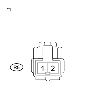
Text in Illustration *1 Front view of wire harness connector
(to Front Seat Outer Belt Assembly LH)
Measure the voltage according to the value(s) in the table below.
Standard Voltage Tester Connection Switch Condition Specified Condition R8-1 - Body ground Power switch on (IG) Below 1 V R8-2 - Body ground Power switch on (IG) Below 1 V -
Disconnect the cable from the negative (-) battery terminal.
-
Reconnect the seat belt control ECU and front seat outer belt assembly LH connectors.
-
Connect the cable to the negative (-) battery terminal.
NG
REPAIR OR REPLACE HARNESS OR CONNECTOR (FRONT SEAT OUTER BELT ASSEMBLY LH - SEAT BELT CONTROL ECU)
OK 
REPLACE SEAT BELT CONTROL ECU Click here
-