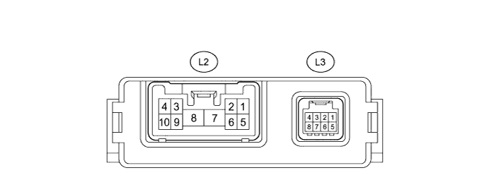
PRE-CRASH SAFETY SYSTEM TERMINALS OF ECU

-
CHECK SEAT BELT CONTROL ECU
-
Disconnect the seat belt control ECU connectors.
-
Measure the resistance and voltage according to the value(s) in the table below.
Terminal No. (Symbol) Wiring Color Terminal Description Condition Specified Condition L2-7 (+B) - Body ground B - Body ground Battery voltage Always 11 to 14 V L2-8 (PGND) - Body ground W-B - Body ground Body ground Always Below 1 Ω L3-8 (IG1) - Body ground R - Body ground Seat belt control ECU power supply Power switch on (IG) 11 to 14 V Power switch off Below 1 V If the result is not as specified, there may be a malfunction on the wire harness side.
-
Reconnect the connectors.
-
Measure the voltage according to the value(s) in the table below.
Terminal No. (Symbol) Wiring Color Terminal Description Condition Specified Condition L2-2 (MOR+) - L2-1 (MOR-) B - W Seat belt motor RH power supply Power switch on (IG) 4.0 to 8.5 V Power switch off Below 1 V L2-3 (MOL+) - L2-4 (MOL-) B - W Seat belt motor LH power supply Power switch on (IG) 4.0 to 8.5 V Power switch off Below 1 V L3-5 (LBL+) - Body ground V - Body ground Front seat inner belt assembly line
-
Power switch on (IG)
-
Fasten passenger side seat belt
Pulse generation
(see waveform 1)
L3-6 (LBL-) - Body ground R - Body ground Front seat inner belt assembly line Always Below 1 Ω If the result is not as specified, the ECU may be malfunctioning.
-
-
Inspect using an oscilloscope.
-
Waveform 1 (Reference)
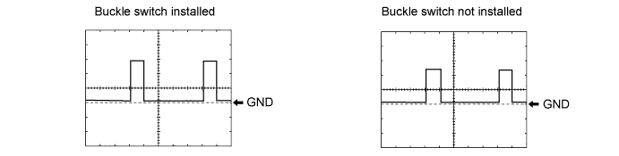
Terminal L3-5 (LBL+) - Body ground Tool Setting 2V/DIV., 20 ms./DIV. Condition Power switch on (IG), buckle switches are not installed Power switch on (IG), buckle switches are installed
-
-
-
CHECK DRIVING SUPPORT ECU

-
Measure the voltage and/or resistance according to the value(s) in the table below.
Terminal No. (Symbols) Wiring Color Terminal Description Condition Specified Condition L60-5 (PBSW) - Body ground L - Body ground Pre crash brake cancel switch Pre crash brake cancel switch ON Below 1 Ω Pre crash brake cancel switch off 10 kΩ or higher L60-17 (CA2L) - L60-25 (GND) W - W-B CAN communication signal Power switch on (IG) Pulse generation
(See waveform 1)
L60-18 (CA1N) - L60-25 (GND) L - W-B CAN communication signal Power switch on (IG) Pulse generation
(See waveform 2)
L60-23 (CCS) - L60-25 (GND) V - W-B Cruise control main switch signal Power switch on (IG) 10 to 14 V L60-23 (CCS) - L60-25 (GND) V - W-B Cruise control main switch signal Power switch on (IG),
CANCEL switch on
6.6 to 10.1 V L60-23 (CCS) - L60-25 (GND) V - W-B Cruise control main switch signal Power switch on (IG),
Main switch on
Below 1 V L60-25 (GND) - Body ground W-B - Body ground Body ground Always Below 1 Ω L60-27 (STP-) - Body ground Y - Body ground Stop light switch signal input Brake pedal depressed 7.5 to 14 V L60-27 (STP-) - Body ground Y - Body ground Stop light switch signal input Brake pedal released Below 1 V L60-28 (ST1-) - Body ground R - Body ground Stop light switch signal input Power switch on (IG),
Brake pedal released
7.5 to 14 V L60-28 (ST1-) - Body ground R - Body ground Stop light switch signal input Power switch on (IG),
Brake pedal depressed
Below 1 V L60-30 (B) - Body ground B - Body ground Power supply Power switch on (IG) 11 to 14 V Power switch off Below 1 V L60-39 (CA2H) - L60-25 (GND) B - W-B CAN communication signal Power switch on (IG) Pulse generation
(See waveform 3)
L60-40 (CA1P) - L60-25 (GND) Y - W-B CAN communication signal Power switch on (IG) Pulse generation
(See waveform 4)
-
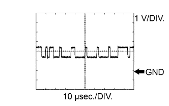
WAVEFORM 1
-
CAN communication signal
Driving support ECU Terminal Name Between CA2L and GND Tester Range 1 V/DIV., 10 μsec./DIV. Condition Power switch on (IG) Tech Tips
The waveform varies depending on the CAN communication signal.
-
-
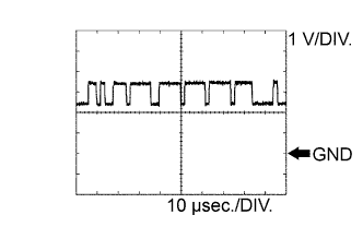
WAVEFORM 2
-
CAN communication signal
Driving support ECU Terminal Name Between CA1N and GND Tester Range 1 V/DIV., 10 μsec./DIV. Condition Power switch on (IG)
-
-
WAVEFORM 3
-
CAN communication signal
Driving support ECU Terminal Name Between CA2H and GND Tester Range 1 V/DIV., 10 μsec./DIV. Condition Power switch on (IG) Tech Tips
The waveform varies depending on the CAN communication signal.
-
-
WAVEFORM 4
-
CAN communication signal
Driving support ECU Terminal Name Between CA1P and GND Tester Range 1 V/DIV., 10 μsec./DIV. Condition Power switch on (IG)
-
-