KNEE AIRBAG ASSEMBLY REMOVAL

-
PRECAUTION
CAUTION:
Be sure to read Precaution thoroughly before servicing Click here.
Note
After turning the power switch off, waiting time may be required before disconnecting the cable from the negative (-) battery terminal. Therefore, make sure to read the disconnecting the cable from the negative (-) battery terminal notices before proceeding with work Click here.
-
REMOVE REAR NO. 2 FLOOR BOARD
-

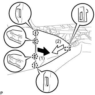
Disengage the 2 guides <A> as shown in the illustration.
-
Disengage the 3 guides <B> and remove the rear No. 2 floor board.
-
-
REMOVE REAR DECK FLOOR BOX
-
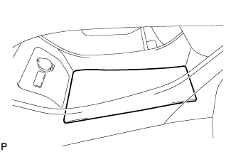
Remove the rear deck floor box.
-
-
REMOVE REAR NO. 3 FLOOR BOARD
-

Disengage the 2 guides and remove the rear No. 3 floor board.
-
-
DISCONNECT CABLE FROM NEGATIVE BATTERY TERMINAL
CAUTION:
Wait at least 90 seconds after disconnecting the cable from the negative (-) battery terminal to disable the SRS system.
Note
When disconnecting the cable, some systems need to be initialized after the cable is reconnected Click here.
-
REMOVE REAR CONSOLE BOX ASSEMBLY
Tech Tips
Refer to the procedure up to Remove Rear Console Box Assembly Click here.
-
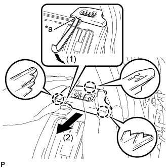
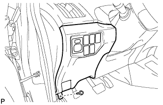
REMOVE INTEGRATION CONTROL AND PANEL ASSEMBLY
-
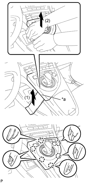
Text in Illustration *a Lift slightly Using a moulding remover, slightly lift the panel at the position shown in the illustration.
-
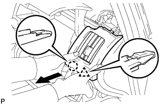
Pull the integration control and panel assembly in the direction indicated by the arrow to disengage the 6 claws.
-
Disconnect each connector and remove the integration control and panel assembly.
-
-
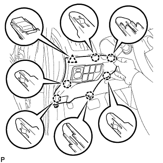
REMOVE LOWER CENTER INSTRUMENT CLUSTER FINISH PANEL SUB-ASSEMBLY
-
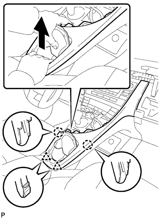
Pull the lower center instrument cluster finish panel sub-assembly in the direction indicated by the arrow to disengage the 2 claws and 2 clips.
-
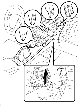
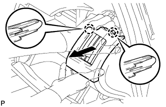
Pull the lower center instrument cluster finish panel sub-assembly in the direction indicated by the arrow to disengage the 5 claws and remove the lower center instrument cluster finish panel sub-assembly.
-
-
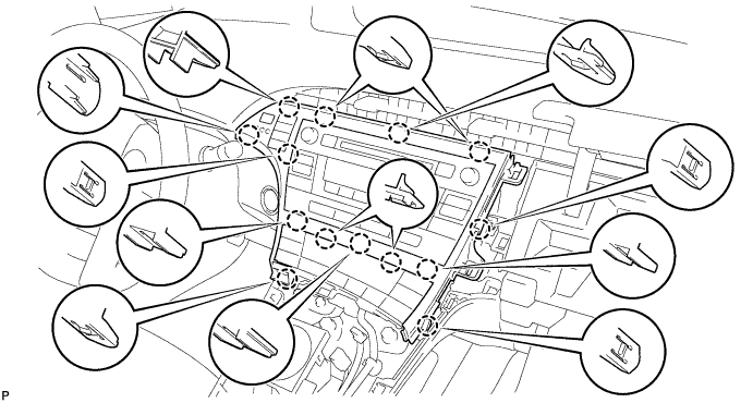
REMOVE INSTRUMENT CLUSTER FINISH PANEL GARNISH
-
Disengage the 14 claws.
-
Disconnect the connector and remove the instrument cluster finish panel garnish.
-
-
REMOVE UPPER INSTRUMENT PANEL FINISH PANEL SUB-ASSEMBLY
-
Disengage the 3 claws.
-
Disconnect the connector and remove the upper instrument panel finish panel sub-assembly.
-
-
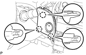
REMOVE CENTER INSTRUMENT CLUSTER FINISH PANEL SUB-ASSEMBLY (w/o Radio Receiver)
-
Disengage the 4 claws and remove the center instrument cluster finish panel sub-assembly.
-
-
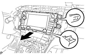
REMOVE RADIO TUNER OPENING COVER WITH BRACKET (w/o Radio Receiver)
-
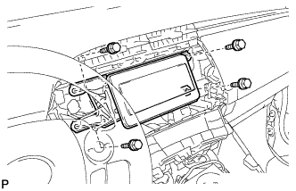
Remove the 4 bolts <B> and radio tuner opening cover with bracket.
-
-
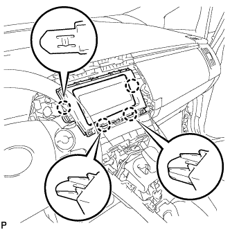
REMOVE RADIO AND DISPLAY RECEIVER ASSEMBLY WITH BRACKET (for Radio and Display Type)
-
Remove the 4 bolts.
-
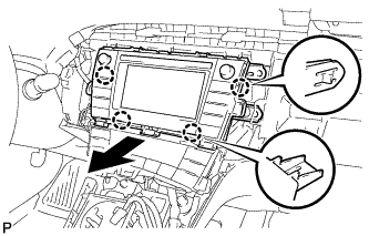
Disengage the 4 claws as shown in the illustration.
-
Disconnect each connector and remove the radio and display receiver assembly with bracket.
-
-
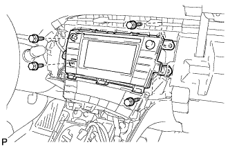
REMOVE NAVIGATION RECEIVER WITH BRACKET (for Navigation Receiver Type)
-
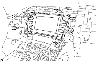
Remove the 4 bolts.
-
Disengage the 4 claws and remove the navigation receiver with bracket as shown in the illustration.
-
Disconnect each connector.
-
-
REMOVE NO. 1 SIDE DEFROSTER NOZZLE
-
Text in Illustration *a Lift slightly Using a moulding remover, slightly lift the panel at the position shown in the illustration.
-
Pull the No. 1 side defroster nozzle in the direction indicated by the arrow to disengage the 3 claws and remove the No. 1 side defroster nozzle.
-
-
REMOVE NO. 2 INSTRUMENT PANEL REGISTER
-
Pull the No. 2 instrument panel register in the direction indicated by the arrow to disengage the claw and clip.
-
Pull the No. 2 instrument panel register in the direction indicated by the arrow to disengage the 2 claws and remove the No. 2 instrument panel register.
-
-
REMOVE GLOVE COMPARTMENT DOOR
-
Open the glove compartment door assembly.
-
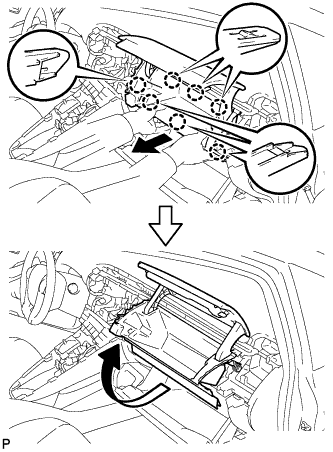
Pull the glove compartment door in the direction indicated by the arrow to disengage the 7 claws.
-
Pull the glove compartment door in the direction indicated by the arrow to remove the glove compartment door.
-
-
REMOVE AIR CONDITIONING CONTROL ASSEMBLY
-
Disengage the 4 claws and remove the air conditioning control assembly as shown in the illustration.
-
Disconnect the connector.
Note
Since the connectors for the air conditioning control assembly and the integration control and panel sub-assembly are the same shape, mark them so that they will not be reconnected incorrectly.
-
-
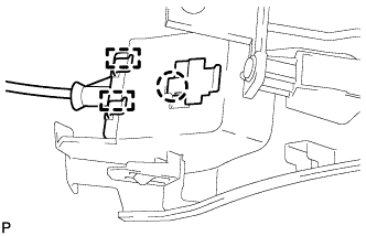
REMOVE SHIFT LOCK CONTROL UNIT ASSEMBLY
-
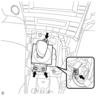
Disconnect the connector from the shift lock control unit assembly.
-
Remove the 3 nuts and shift lock control unit assembly.
-
-
REMOVE ELECTRICAL KEY OSCILLATOR
-
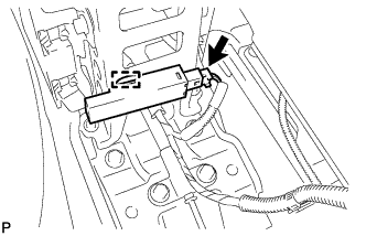
Disconnect the connector.
-
Disengage the clamp and remove the electrical key oscillator.
Note
Be careful when removing the electrical key oscillator. If the oscillator is dropped, replace it with a new one.
-
-
REMOVE NO. 2 CONSOLE BOX MOUNTING BRACKET
-
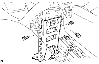
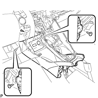
Remove the 6 bolts <B> and No. 2 console box mounting bracket.
-
-
REMOVE FRONT NO. 1 CONSOLE BOX INSERT
-
Pull the front No. 1 console box insert in the direction indicated by the arrow to disengage the 4 claws and guide, and remove the front No. 1 console box insert.
-
-
REMOVE FRONT NO. 2 CONSOLE BOX INSERT
-
Pull the front No. 2 console box insert in the direction indicated by the arrow to disengage the 4 claws and guide, and remove the front No. 2 console box insert.
-
-
REMOVE BOX BOTTOM MAT
-
Disengage the fastener and remove the box bottom mat.
-
-
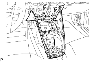
SEPARATE CONSOLE BOX ASSEMBLY
-
Remove the bolt <B> and 2 clips.
-
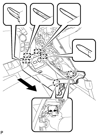
While pushing the parts shown in the illustration inward, pull the console box assembly in the direction indicated by the arrow to disengage the 2 claws and 4 guides.
-
Disconnect the connector and separate the console box assembly.
-
-
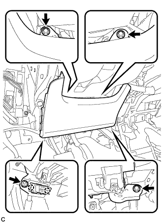
REMOVE UPPER INSTRUMENT PANEL FINISH PANEL ASSEMBLY
-
Disengage the clamp.
-
Remove the 2 bolts <A>.
-
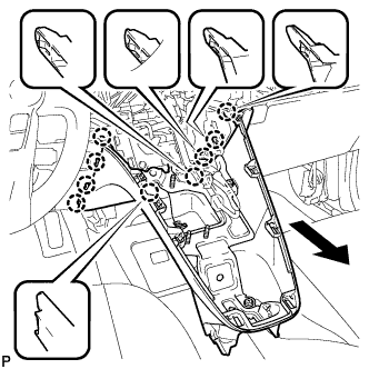
Pull the upper instrument panel finish panel assembly in the direction indicated by the arrow to disengage the 9 claws and remove the upper instrument panel finish panel assembly.
-
-
REMOVE CONSOLE BOX ASSEMBLY
-
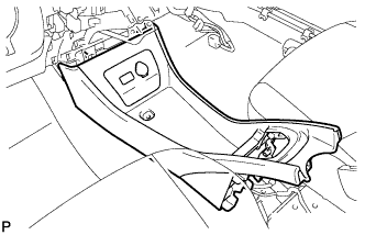
Remove the console box assembly.
-
-
REMOVE NO. 1 SWITCH HOLE BASE
-
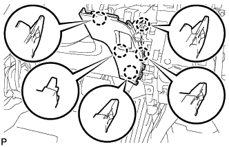
Disengage the 5 claws.
-
Disconnect the connector to remove the No. 1 switch hole base.
-
-
REMOVE FRONT DOOR SCUFF PLATE LH
-
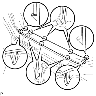
Disengage the 10 claws and remove the front door scuff plate LH.
-
-
REMOVE COWL SIDE TRIM SUB-ASSEMBLY LH
-
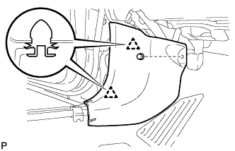
Remove the clip.
-
Disengage the 2 clips and remove the cowl side trim sub-assembly LH.
-
-
REMOVE NO. 1 INSTRUMENT PANEL UNDER COVER SUB-ASSEMBLY (for LHD)
-
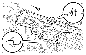
Remove the 2 screws <D>.
-
Disengage the claw and guide.
-
Disconnect each connector and remove the No. 1 instrument panel under cover sub-assembly.
-
-
REMOVE NO. 1 INSTRUMENT PANEL UNDER COVER SUB-ASSEMBLY (for RHD)
-
Remove the screw <D>.
-
Disengage the 2 claws and guide.
-
Disconnect each connector and remove the No. 1 instrument panel under cover sub-assembly.
-
-
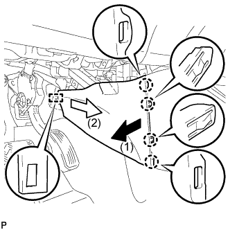
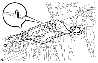
REMOVE LOWER INSTRUMENT PANEL FINISH PANEL ASSEMBLY
-
Remove the screw <C>.
-
Disengage the 6 claws and clip as shown in the illustration.
-
Disengage the claw and 2 guides and disconnect the hood lock control cable.
-
Disconnect each connector and clamp, and remove the lower instrument panel finish panel assembly.
-
-
REMOVE DRIVER SIDE KNEE AIRBAG ASSEMBLY
CAUTION:
When storing the driver side knee airbag assembly, keep the airbag deployment side facing upward.
-
Check that the power switch is off.
-
Check that the cable is disconnected from the negative (-) battery terminal.
CAUTION:
Wait at least 90 seconds after disconnecting the cable from the negative (-) battery terminal to disable the SRS system.
-
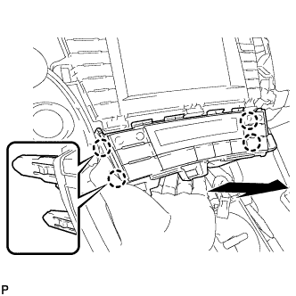
Remove the 4 bolts.
-
Disengage the 2 claws to separate the DLC3.
-
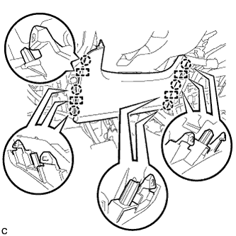
Disengage the 6 claws and 4 guides to separate the driver side knee airbag assembly.
-
Disengage the clamp to separate the wire harness.
-
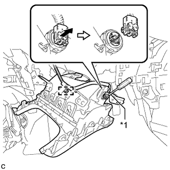
Using a screwdriver with the tip wrapped with protective tape, release the airbag connector lock.
Text in Illustration *1 Protective Tape -
Disconnect the airbag connector to remove the driver side knee airbag assembly.
Note
When disconnecting any airbag connector, take care not to damage the airbag wire harness.
-