AIRBAG SYSTEM, Diagnostic DTC:B1660/43

| DTC Code | DTC Name |
|---|---|
| B1660/43 | Passenger Airbag ON/OFF Indicator Circuit Malfunction |
DESCRIPTION
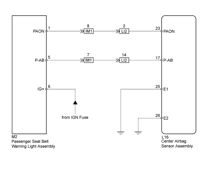
The passenger airbag ON/OFF indicator circuit consists of the center airbag sensor assembly and passenger seat belt warning light assembly (passenger airbag ON/OFF indicator).
The passenger airbag ON/OFF indicator indicates the operation condition of the front passenger airbag.
DTC B1660/43 is stored when a malfunction is detected in the passenger airbag ON/OFF indicator circuit.
| DTC No. | DTC Detection Condition | Trouble Area |
|---|---|---|
| B1660/43 |
|
|
WIRING DIAGRAM
INSPECTION PROCEDURE
PROCEDURE
-
CHECK PASSENGER AIRBAG ON/OFF INDICATOR CONDITION
-
Turn the power switch on (IG).
-
Check the passenger airbag ON/OFF indicator operation.
Tech Tips
Refer to the normal condition of the passenger airbag ON/OFF indicator Click here.
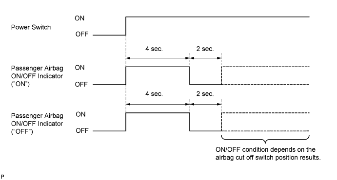
Result ON/OFF Indicator Illumination Proceed to Always ON A OFF B
B 
CHECK CONNECTORS Click here
A 
-
-
CHECK CONNECTORS
-
Turn the power switch off.
-
Disconnect the cable from the negative (-) battery terminal.
CAUTION:
Wait at least 90 seconds after disconnecting the cable from the negative (-) battery terminal to disable the SRS system.
-
Check that the connectors are properly connected to the center airbag sensor assembly and passenger seat belt warning light assembly. Also check that the connectors that link the instrument panel wire, No. 2 instrument panel wire and No. 5 instrument panel wire are properly connected.
OK The connectors are properly connected. Tech Tips
If the connectors are not connected securely, reconnect the connectors and proceed to the next inspection.
-
Disconnect the connectors from the center airbag sensor assembly and passenger seat belt warning light assembly. Also disconnect the connectors that link the instrument panel wire, No. 2 instrument panel wire and No. 5 instrument panel wire.
-
Check that the terminals of connectors are not damaged.
OK The terminals are not deformed or damaged.
NG 
REPLACE WIRE HARNESS
OK
-
-
CHECK PASSENGER AIRBAG ON/OFF INDICATOR
-
Connect the connectors that link the instrument panel wire, No. 2 instrument panel wire and No. 5 instrument panel wire.
-
Connect the connector to the passenger seat belt warning light assembly.
-
Connect the cable to the negative (-) battery terminal.
-
Turn the power switch on (IG).
-
Check the passenger airbag ON/OFF indicator operation.
OK The passenger airbag ON/OFF indicator does not come on.
NG
CHECK PASSENGER AIRBAG ON/OFF INDICATOR CIRCUIT (OPEN) Click here
OK
-
-
CHECK CENTER AIRBAG SENSOR ASSEMBLY
-
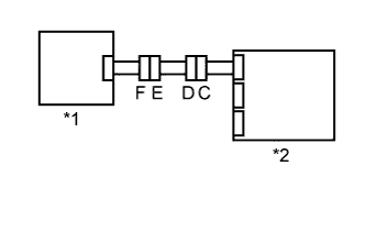
Text in Illustration *1 Passenger Seat Belt Warning Light Assembly *2 Center Airbag Sensor Assembly Connect the connector to the center airbag sensor assembly.
-
Connect the cable to the negative (-) battery terminal.
-
Turn the power switch on (IG), and wait for at least 60 seconds.
-
Clear the DTCs stored in the memory Click here.
-
Turn the power switch off.
-
Turn the power switch on (IG), and wait for at least 60 seconds.
-
Check for DTCs Click here.
OK DTC B1660/43 is not output. Tech Tips
Codes other than DTC B1660/43 may be output at this time, but they are not related to this check.
NG
REPLACE CENTER AIRBAG SENSOR ASSEMBLY Click here
OK 
USE SIMULATION METHOD TO CHECK Click here
-
-
CHECK PASSENGER AIRBAG ON/OFF INDICATOR CIRCUIT (OPEN)
-
Turn the power switch off.
-
Disconnect the cable from the negative (-) battery terminal.
CAUTION:
Wait at least 90 seconds after disconnecting the cable from the negative (-) battery terminal to disable the SRS system.
-
Connect the connectors that link the instrument panel wire, No. 2 instrument panel wire and No. 5 instrument panel wire.
-
Disconnect the connector from the passenger seat belt warning light assembly.
-
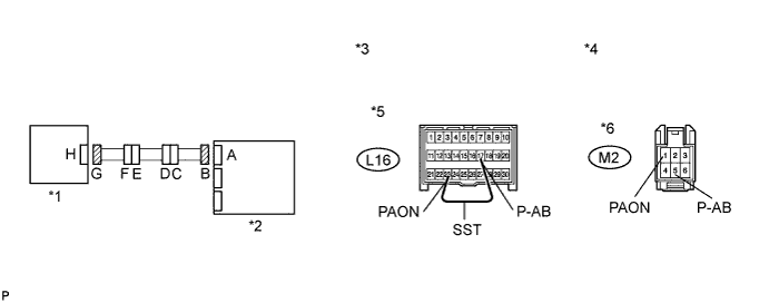
Using SST, connect terminals 23 (PAON) and 17 (P-AB) of connector B.
Note
Do not forcibly insert SST into the terminals of the connector when connecting the wire.
- SST
- 09843-18040
-
Measure the resistance according to the value(s) in the table below.
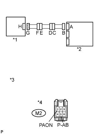
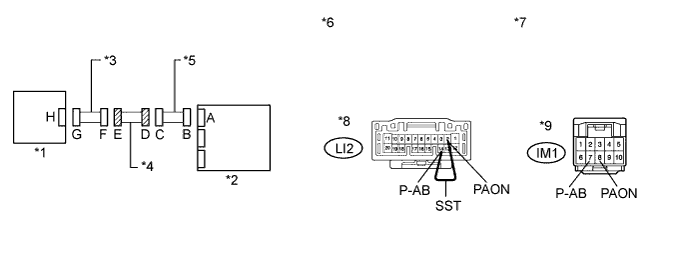
Standard Resistance Tester Connection Condition Specified Condition M2-1 (PAON) - M2-5 (P-AB) Always Below 1 Ω Text in Illustration *1 Passenger Seat Belt Warning Light Assembly *2 Center Airbag Sensor Assembly *3 Front view of wire harness connector
(to Center Airbag Sensor Assembly)
*4 Front view of wire harness connector
(to Passenger Seat Belt Warning Light Assembly)
*5 Connector B *6 Connector G
NG
CHECK INSTRUMENT PANEL WIRE (OPEN) Click here
OK
-
-
CHECK PASSENGER AIRBAG ON/OFF INDICATOR CIRCUIT (SHORT)
-
Text in Illustration *1 Passenger Seat Belt Warning Light Assembly *2 Center Airbag Sensor Assembly *3 Front view of wire harness connector
(to Passenger Seat Belt Warning Light Assembly)
*4 Connector G Disconnect SST from connector B.
-
Measure the resistance according to the value(s) in the table below.
Standard Resistance Tester Connection Condition Specified Condition M2-1 (PAON) - M2-5 (P-AB) Always 1 MΩ or higher
NG
CHECK INSTRUMENT PANEL WIRE (SHORT) Click here
OK
-
-
CHECK PASSENGER AIRBAG ON/OFF INDICATOR CIRCUIT (SHORT TO GROUND)
-
Text in Illustration *1 Passenger Seat Belt Warning Light Assembly *2 Center Airbag Sensor Assembly *3 Front view of wire harness connector
(to Passenger Seat Belt Warning Light Assembly)
*4 Connector G Measure the resistance according to the value(s) in the table below.
Standard Resistance Tester Connection Condition Specified Condition M2-1 (PAON) - Body ground Always 1 MΩ or higher M2-5 (P-AB) - Body ground Always 1 MΩ or higher
NG
CHECK INSTRUMENT PANEL WIRE (SHORT TO GROUND) Click here
OK
-
-
CHECK PASSENGER AIRBAG ON/OFF INDICATOR CIRCUIT (SHORT TO B+)
-
Text in Illustration *1 Passenger Seat Belt Warning Light Assembly *2 Center Airbag Sensor Assembly *3 Front view of wire harness connector
(to Passenger Seat Belt Warning Light Assembly)
*4 Connector G Connect the cable to the negative (-) battery terminal.
-
Turn the power switch on (IG).
-
Measure the voltage according to the value(s) in the table below.
Standard Voltage Tester Connection Switch Condition Specified Condition M2-1 (PAON) - Body ground Power switch on (IG) Below 1 V M2-5 (P-AB) - Body ground Power switch on (IG) Below 1 V
NG
CHECK INSTRUMENT PANEL WIRE (SHORT TO B+) Click here
OK
REPLACE CENTER AIRBAG SENSOR ASSEMBLY Click here
-
-
CHECK CONNECTORS
-
Turn the power switch off.
-
Disconnect the cable from the negative (-) battery terminal.
CAUTION:
Wait at least 90 seconds after disconnecting the cable from the negative (-) battery terminal to disable the SRS system.
-
Check that the connectors are properly connected to the center airbag sensor assembly and passenger seat belt warning light assembly. Also check that the connectors that link the instrument panel wire, No. 2 instrument panel wire and No. 5 instrument panel wire are properly connected.
OK The connectors are properly connected. Tech Tips
If the connectors are not connected securely, reconnect the connectors and proceed to the next inspection.
-
Disconnect the connectors from the center airbag sensor assembly and passenger seat belt warning light assembly. Also disconnect the connectors that link the instrument panel wire, No. 2 instrument panel wire and No. 5 instrument panel wire.
-
Check that the terminals of connectors are not damaged.
OK The terminals are not deformed or damaged.
NG
REPLACE WIRE HARNESS
OK
-
-
CHECK PASSENGER AIRBAG ON/OFF INDICATOR CIRCUIT (OPEN)
-
Connect the connectors that link the instrument panel wire, No. 2 instrument panel wire and No. 5 instrument panel wire.
-
Using SST, connect terminals 23 (PAON) and 17 (P-AB) of connector B.
Note
Do not forcibly insert SST into the terminals of the connector when connecting the wire.
- SST
- 09843-18040
-
Measure the resistance according to the value(s) in the table below.
Standard Resistance Tester Connection Condition Specified Condition M2-1 (PAON) - M2-5 (P-AB) Always Below 1 Ω Text in Illustration *1 Passenger Seat Belt Warning Light Assembly *2 Center Airbag Sensor Assembly *3 Front view of wire harness connector
(to Center Airbag Sensor Assembly)
*4 Front view of wire harness connector
(to Passenger Seat Belt Warning Light Assembly)
*5 Connector B *6 Connector G
NG
CHECK INSTRUMENT PANEL WIRE (OPEN) Click here
OK
-
-
CHECK PASSENGER AIRBAG ON/OFF INDICATOR CIRCUIT (SHORT)
-
Text in Illustration *1 Passenger Seat Belt Warning Light Assembly *2 Center Airbag Sensor Assembly *3 Front view of wire harness connector
(to Passenger Seat Belt Warning Light Assembly)
*4 Connector G Disconnect SST from connector B.
-
Measure the resistance according to the value(s) in the table below.
Standard Resistance Tester Connection Condition Specified Condition M2-1 (PAON) - M2-5 (P-AB) Always 1 MΩ or higher
NG
CHECK INSTRUMENT PANEL WIRE (SHORT) Click here
OK
-
-
CHECK PASSENGER AIRBAG ON/OFF INDICATOR CIRCUIT (SHORT TO GROUND)
-
Text in Illustration *1 Passenger Seat Belt Warning Light Assembly *2 Center Airbag Sensor Assembly *3 Front view of wire harness connector
(to Passenger Seat Belt Warning Light Assembly)
*4 Connector G Measure the resistance according to the value(s) in the table below.
Standard Resistance Tester Connection Condition Specified Condition M2-1 (PAON) - Body ground Always 1 MΩ or higher M2-5 (P-AB) - Body ground Always 1 MΩ or higher
NG
CHECK INSTRUMENT PANEL WIRE (SHORT TO GROUND) Click here
OK
-
-
CHECK PASSENGER AIRBAG ON/OFF INDICATOR CIRCUIT (SHORT TO B+)
-
Text in Illustration *1 Passenger Seat Belt Warning Light Assembly *2 Center Airbag Sensor Assembly *3 Front view of wire harness connector
(to Passenger Seat Belt Warning Light Assembly)
*4 Connector G Connect the cable to the negative (-) battery terminal.
-
Turn the power switch on (IG).
-
Measure the voltage according to the value(s) in the table below.
Standard Voltage Tester Connection Switch Condition Specified Condition M2-1 (PAON) - Body ground Power switch on (IG) Below 1 V M2-5 (P-AB) - Body ground Power switch on (IG) Below 1 V
NG
CHECK INSTRUMENT PANEL WIRE (SHORT TO B+) Click here
OK
-
-
CHECK PASSENGER SEAT BELT WARNING LIGHT ASSEMBLY (SOURCE VOLTAGE)
-
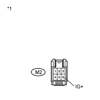
Text in Illustration *1 Front view of wire harness connector
(to Passenger Seat Belt Warning Light Assembly)
Turn the power switch on (IG).
-
Measure the voltage according to the value(s) in the table below.
Standard Voltage Tester Connection Switch Condition Specified Condition M2-6 (IG+) - Body ground Power switch on (IG) 10 to 14 V
NG
REPLACE WIRE HARNESS OR BATTERY
OK
-
-
CHECK PASSENGER AIRBAG ON/OFF INDICATOR
-
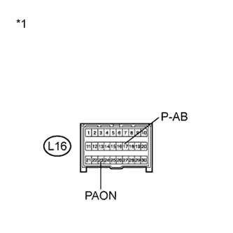
Text in Illustration *1 Front view of wire harness connector
(to Center Airbag Sensor Assembly)
Turn the power switch off.
-
Disconnect the cable from the negative (-) battery terminal.
CAUTION:
Wait at least 90 seconds after disconnecting the cable from the negative (-) battery terminal to disable the SRS system.
-
Connect the connector to the passenger seat belt warning light assembly.
-
Connect the cable to the negative (-) battery terminal.
-
Turn the power switch on (IG).
-
Check the indicator according to the conditions in the table below.
Result Tester Connection Switch Condition Specified Condition L16-23 (PAON) - Body ground Power switch on (IG) "ON" comes on L16-17 (P-AB) - Body ground Power switch on (IG) "OFF" comes on
NG
REPLACE PASSENGER SEAT BELT WARNING LIGHT ASSEMBLY Click here
OK
-
-
CHECK CENTER AIRBAG SENSOR ASSEMBLY
-
Text in Illustration *1 Passenger Seat Belt Warning Light Assembly *2 Center Airbag Sensor Assembly Turn the power switch off.
-
Disconnect the cable from the negative (-) battery terminal.
CAUTION:
Wait at least 90 seconds after disconnecting the cable from the negative (-) battery terminal to disable the SRS system.
-
Connect the connector to the center airbag sensor assembly.
-
Connect the cable to the negative (-) battery terminal.
-
Turn the power switch on (IG), and wait for at least 60 seconds.
-
Clear the DTCs stored in the memory Click here.
-
Turn the power switch off.
-
Turn the power switch on (IG), and wait for at least 60 seconds.
-
Check for DTCs Click here.
OK DTC B1660/43 is not output. Tech Tips
Codes other than DTC B1660/43 may be output at this time, but they are not related to this check.
NG
REPLACE CENTER AIRBAG SENSOR ASSEMBLY Click here
OK
USE SIMULATION METHOD TO CHECK Click here
-
-
CHECK INSTRUMENT PANEL WIRE (OPEN)
-
Disconnect the instrument panel wire from the No. 2 instrument panel wire.
Tech Tips
SST has already been inserted into connector B.
-
Measure the resistance according to the value(s) in the table below.
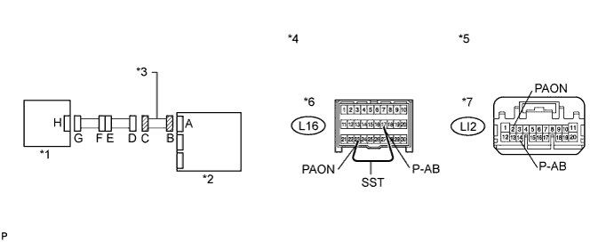
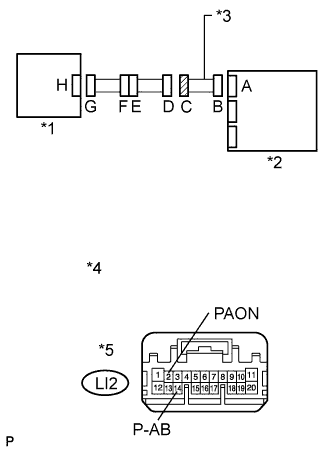
Standard Resistance Tester Connection Condition Specified Condition LI2-2 (PAON) - LI2-14 (P-AB) Always Below 1 Ω Text in Illustration *1 Passenger Seat Belt Warning Light Assembly *2 Center Airbag Sensor Assembly *3 Instrument Panel Wire *4 Front view of wire harness connector
(to Center Airbag Sensor Assembly)
*5 Front view of wire harness connector
(to No. 2 Instrument Panel Wire)
*6 Connector B *7 Connector C - -
NG
REPLACE INSTRUMENT PANEL WIRE
OK
-
-
CHECK NO. 2 INSTRUMENT PANEL WIRE (OPEN)
-
Disconnect the No. 2 instrument panel wire from the No. 5 instrument panel wire.
-
Using SST, connect terminals 2 (PAON) and 14 (P-AB) of connector D.
Note
Do not forcibly insert SST into the terminals of the connector when connecting.
- SST
- 09843-18040
-
Measure the resistance according to the value(s) in the table below.
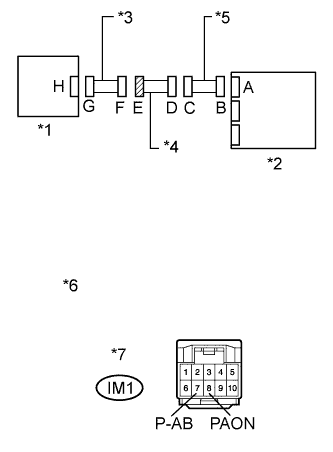
Standard Resistance Tester Connection Condition Specified Condition IM1-8 (PAON) - IM1-7 (P-AB) Always Below 1 Ω Text in Illustration *1 Passenger Seat Belt Warning Light Assembly *2 Center Airbag Sensor Assembly *3 No. 5 Instrument Panel Wire *4 No. 2 Instrument Panel Wire *5 Instrument Panel Wire *6 Front view of wire harness connector
(to Instrument Panel Wire)
*7 Front view of wire harness connector
(to No. 5 Instrument Panel Wire)
*8 Connector D *9 Connector E - -
NG
REPLACE NO. 2 INSTRUMENT PANEL WIRE
OK
REPLACE NO. 5 INSTRUMENT PANEL WIRE
-
-
CHECK INSTRUMENT PANEL WIRE (SHORT)
-
Text in Illustration *1 Passenger Seat Belt Warning Light Assembly *2 Center Airbag Sensor Assembly *3 Instrument Panel Wire *4 Front view of wire harness connector
(to No. 2 Instrument Panel Wire)
*5 Connector C Disconnect the instrument panel wire from the No. 2 instrument panel wire.
-
Measure the resistance according to the value(s) in the table below.
Standard Resistance Tester Connection Switch Condition Specified Condition LI2-2 (PAON) - LI2-14 (P-AB) Always 1 MΩ or higher
NG
REPLACE INSTRUMENT PANEL WIRE
OK
-
-
CHECK NO. 2 INSTRUMENT PANEL WIRE (SHORT)
-
Text in Illustration *1 Passenger Seat Belt Warning Light Assembly *2 Center Airbag Sensor Assembly *3 No. 5 Instrument Panel Wire *4 No. 2 Instrument Panel Wire *5 Instrument Panel Wire *6 Front view of wire harness connector
(to No. 5 Instrument Panel Wire)
*7 Connector E Disconnect the No. 2 instrument panel wire from the No. 5 instrument panel wire.
-
Measure the resistance according to the value(s) in the table below.
Standard Resistance Tester Connection Condition Specified Condition IM1-8 (PAON) - IM1-7 (P-AB) Always 1 MΩ or higher
NG
REPLACE NO. 2 INSTRUMENT PANEL WIRE
OK
REPLACE NO. 5 INSTRUMENT PANEL WIRE
-
-
CHECK INSTRUMENT PANEL WIRE (SHORT TO GROUND)
-
Text in Illustration *1 Passenger Seat Belt Warning Light Assembly *2 Center Airbag Sensor Assembly *3 Instrument Panel Wire *4 Front view of wire harness connector
(to No. 2 Instrument Panel Wire)
*5 Connector C Disconnect the instrument panel wire from the No. 2 instrument panel wire.
-
Measure the resistance according to the value(s) in the table below.
Standard Resistance Tester Connection Condition Specified Condition LI2-2 (PAON) - Body ground Always 1 MΩ or higher LI2-14 (P-AB) - Body ground Always 1 MΩ or higher
NG
REPLACE INSTRUMENT PANEL WIRE
OK
-
-
CHECK NO. 2 INSTRUMENT PANEL WIRE (SHORT TO GROUND)
-
Text in Illustration *1 Passenger Seat Belt Warning Light Assembly *2 Center Airbag Sensor Assembly *3 No. 5 Instrument Panel Wire *4 No. 2 Instrument Panel Wire *5 Instrument Panel Wire *6 Front view of wire harness connector
(to No. 5 Instrument Panel Wire)
*7 Connector E Disconnect the No. 2 instrument panel wire from the No. 5 instrument panel wire.
-
Measure the resistance according to the value(s) in the table below.
Standard Resistance Tester Connection Condition Specified Condition IM1-8 (PAON) - Body ground Always 1 MΩ or higher IM1-7 (P-AB) - Body ground Always 1 MΩ or higher
NG
REPLACE NO. 2 INSTRUMENT PANEL WIRE
OK
REPLACE NO. 5 INSTRUMENT PANEL WIRE
-
-
CHECK INSTRUMENT PANEL WIRE (SHORT TO B+)
-
Text in Illustration *1 Passenger Seat Belt Warning Light Assembly *2 Center Airbag Sensor Assembly *3 Instrument Panel Wire *4 Front view of wire harness connector
(to No. 2 Instrument Panel Wire)
*5 Connector C Turn the power switch off.
-
Disconnect the cable from the negative (-) battery terminal.
CAUTION:
Wait at least 90 seconds after disconnecting the cable from the negative (-) battery terminal to disable the SRS system.
-
Disconnect the instrument panel wire from the No. 2 instrument panel wire.
-
Connect the cable to the negative (-) battery terminal.
-
Turn the power switch on (IG).
-
Measure the voltage according to the value(s) in the table below.
Standard Voltage Tester Connection Switch Condition Specified Condition LI2-2 (PAON) - Body ground Power switch on (IG) Below 1 V LI2-14 (P-AB) - Body ground Power switch on (IG) Below 1 V
NG
REPLACE INSTRUMENT PANEL WIRE
OK
-
-
CHECK NO. 2 INSTRUMENT PANEL WIRE (SHORT TO B+)
-
Text in Illustration *1 Passenger Seat Belt Warning Light Assembly *2 Center Airbag Sensor Assembly *3 No. 5 Instrument Panel Wire *4 No. 2 Instrument Panel Wire *5 Instrument Panel Wire *6 Front view of wire harness connector
(to No. 5 Instrument Panel Wire)
*7 Connector E Turn the power switch off.
-
Disconnect the cable from the negative (-) battery terminal.
CAUTION:
Wait at least 90 seconds after disconnecting the cable from the negative (-) battery terminal to disable the SRS system.
-
Disconnect the No. 2 instrument panel wire from the No. 5 instrument panel wire.
-
Connect the cable to the negative (-) battery terminal.
-
Turn the power switch on (IG).
-
Measure the voltage according to the value(s) in the table below.
Standard Voltage Tester Connection Switch Condition Specified Condition IM1-8 (PAON) - Body ground Power switch on (IG) Below 1 V IM1-7 (P-AB) - Body ground Power switch on (IG) Below 1 V
NG
REPLACE NO. 2 INSTRUMENT PANEL WIRE
OK
REPLACE NO. 5 INSTRUMENT PANEL WIRE
-