TRIP SWITCH INSPECTION

-
INSPECT TRIP SWITCH
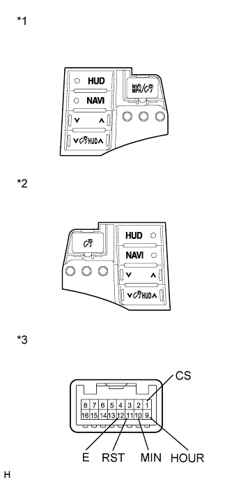
Text in Illustration *1 Trip Switch (for RHD) *2 Trip Switch (for LHD) *1 Component without harness connected
(Trip Switch)
-
Measure the resistance according to the value(s) in the table below.
Standard Resistance Tester Connection Condition Specified Condition 1 (CS) - 12 (E) Unit change switch pressed Below 1 Ω 1 (CS) - 12 (E) Unit change switch not pressed 10 kΩ or higher 9 (HOUR) - 12 (E) Hour adjust switch pressed Below 1 Ω 9 (HOUR) - 12 (E) Hour adjust switch not pressed 10 kΩ or higher 10 (MIN) - 12 (E) Minute adjust switch pressed Below 1 Ω 10 (MIN) - 12 (E) Minute adjust switch not pressed 10 kΩ or higher 11 (RST) - 12 (E) Set switch pressed Below 1 Ω 11 (RST) - 12 (E) Set switch not pressed 10 kΩ or higher -
Apply battery voltage from the wire harness back side between the terminals of the switch, and check the lighting condition of the trip switch.
OK Measurement Condition Condition Specified Condition Battery positive (+) → 8 (ILL+)
Battery negative (-) → 4 (E)
Always Trip switch illuminates If the result is not as specified, replace the trip switch Click here.
-