METER / GAUGE SYSTEM Headup Display Malfunction
DESCRIPTION
This circuit is the power source circuit for the headup display (combination meter mirror ECU). This circuit provides two types of power sources; one is a constant power source, and the other is a IG power source.
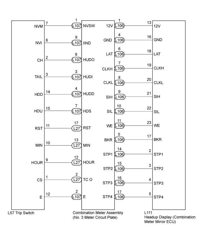
WIRING DIAGRAM
INSPECTION PROCEDURE
Tech Tips
Before starting the following inspection, confirm the headup display (combination meter mirror ECU) position and illuminance, then perform the on-vehicle inspection Click here.
PROCEDURE
-
SYSTEM CHECK
-
Check the symptom of the headup display (combination meter mirror ECU).
Result Result Proceed to Headup display (combination meter mirror ECU) does not operate at all. A Cruise information display does not change. B
B 
READ VALUE USING INTELLIGENT TESTER Click here
A 
-
-
CHECK HARNESS AND CONNECTOR (HEADUP DISPLAY CIRCUIT)
-
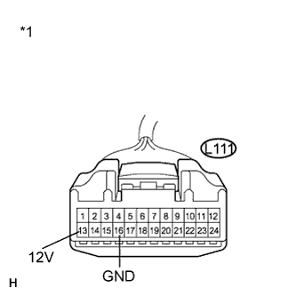
Text in Illustration *1 Front view of wire harness connector
(to Headup Display (Combination Meter Mirror ECU))
Disconnect the L111 connector.
-
Measure the voltage according to the value(s) in the table below.
Standard Voltage Tester Connection Condition Specified Condition L111-13 (12V) - Body ground Power switch on (IG) 11 to 14 V -
Measure the resistance according to the value(s) in the table below
Standard Resistance Tester Connection Condition Specified Condition L111-16 (GND) - Body ground Always Below 1 Ω
NG 
REPAIR OR REPLACE HARNESS OR CONNECTOR
OK 
REPLACE HEADUP DISPLAY (COMBINATION METER MIRROR ECU) Click here
-
-
READ VALUE USING INTELLIGENT TESTER
-
Connect the intelligent tester to the DLC3.
-
Turn the power switch on (IG).
-
Turn the intelligent tester ON.
-
Enter the following menus: Body / Combination Meter / Data List.
-
Check the values by referring to the table below.
Combination Meter Tester Display Measurement Item/Range Normal Condition Diagnostic Note Head Up Display Switch (Up) Headup display position up switch condition OFF: Headup display position up switch not pressed - ON: Headup display position up switch pressed - Head Up Display Switch (Down) Headup display position down switch condition OFF: Headup display position down switch not pressed - ON: Headup display position down switch pressed - Head Up Display Switch (Main) Headup display main switch condition OFF: Headup display main switch not pressed - ON: Headup display main switch pressed - OK Each switch condition displayed on the intelligent tester changes with the actual switch operation.
B
CHECK HARNESS AND CONNECTOR (HEADUP DISPLAY - NO. 3 METER CIRCUIT PLATE) Click here
A
REPLACE COMBINATION METER ASSEMBLY (NO. 3 METER CIRCUIT PLATE) Click here
-
-
CHECK HARNESS AND CONNECTOR (HEADUP DISPLAY - NO. 3 METER CIRCUIT PLATE)
-
Disconnect the L111 and L57 connectors.
-
Measure the resistance according to the value(s) in the table below.
Standard Resistance Tester Connection Condition Specified Condition L111-17 (BKR) - L106-5 (BKR) Always Below 1 Ω L111-17 (BKR) - Body ground Always 10 kΩ or higher L111-18 (LAT) - L106-6 (LAT) Always Below 1 Ω L111-18 (LAT) - Body ground Always 10 kΩ or higher L111-19 (CLKH) - L106-7 (CLKH) Always Below 1 Ω L111-19 (CLKH) - Body ground Always 10 kΩ or higher L111-20 (CLKL) - L106-8 (CLKL) Always Below 1 Ω L111-20 (CLKL) - Body ground Always 10 kΩ or higher L111-21 (SIH) - L106-9 (SIH) Always Below 1 Ω L111-21 (SIH) - Body ground Always 10 kΩ or higher L111-22 (SIL) - L106-10 (SIL) Always Below 1 Ω L111-22 (SIL) - Body ground Always 10 kΩ or higher L111-23 (WE) - L106-11 (WE) Always Below 1 Ω L111-23 (WE) - Body ground Always 10 kΩ or higher L111-2 (STP1) - L106-14 (STP1) Always Below 1 Ω L111-2 (STP1) - Body ground Always 10 kΩ or higher L111-3 (STP2) - L106-15 (STP2) Always Below 1 Ω L111-3 (STP2) - Body ground Always 10 kΩ or higher L111-4 (STP3) - L106-16 (STP3) Always Below 1 Ω L111-4 (STP3) - Body ground Always 10 kΩ or higher L111-5 (STP4) - L106-17 (STP4) Always Below 1 Ω L111-5 (STP4) - Body ground Always 10 kΩ or higher
NG
REPAIR OR REPLACE HARNESS OR CONNECTOR
OK
-
-
INSPECT TRIP SWITCH
-
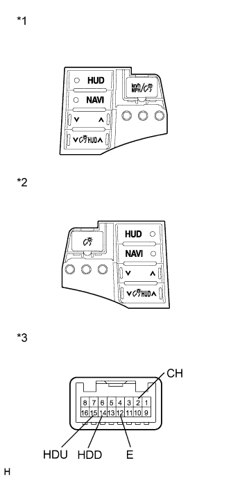
Text in Illustration *1 Component without harness connected
(Trip Switch)
Disconnect the L57 connector.
-
Measure the resistance according to the value(s) in the table below.
Standard Resistance Tester Connection Switch Condition Specified Condition 2 (CH) - 12 (E) HUD/MODE switch pressed Below 1 Ω 2 (CH) - 12 (E) Always 10 kΩ or higher 12 (E) - 14 (HDD) Down switch pressed Below 1 Ω 12 (E) - 14 (HDD) Always 10 kΩ or higher 12 (E) - 15 (HDU) Up switch pressed Below 1 Ω 12 (E) - 15 (HDU) Always 10 kΩ or higher
NG
REPLACE TRIP SWITCH Click here
OK
-
-
CHECK HARNESS AND CONNECTOR (TRIP SWITCH - NO. 3 METER CIRCUIT PLATE)
-
Disconnect the L27, L57, and L107 connectors.
-
Measure the resistance according to the value(s) in the table below.
Standard Resistance Tester Connection Condition Specified Condition L57-1 (CS) - L27-2 (TC O) Always Below 1 Ω L57-1 (CS) - Body ground Always 10 kΩ or higher L57-9 (HOUR) - L27-12 (HOUR) Always Below 1 Ω L57-9 (HOUR) - Body ground Always 10 kΩ or higher L57-10 (MIN) - L27-13 (MIN) Always Below 1 Ω L57-10 (HOUR) - Body ground Always 10 kΩ or higher L57-11 (RST) - L27-17 (RST) Always Below 1 Ω L57-11 (RST) - Body ground Always 10 kΩ or higher L57-12 (E) - L107-2 (E) Always Below 1 Ω L57-12 (E) - Body ground Always 10 kΩ or higher L57-15 (HDU) - L107-7 (HDS) Always Below 1 Ω L57-15 (HDU) - Body ground Always 10 kΩ or higher L57-14 (HDD) - L107-4 (HUDD) Always Below 1 Ω L57-14 (HDD) - Body ground Always 10 kΩ or higher L57-3 (TAIL) - L107-3 (HUDI) Always Below 1 Ω L57-3 (TAIL) - Body ground Always 10 kΩ or higher L57-2 (CH) - L107-8 (HUDO) Always Below 1 Ω L57-2 (CH) - Body ground Always 10 kΩ or higher L57-6 (NVI) - L107-9 (IIND) Always Below 1 Ω L57-6 (NVI) - Body ground Always 10 kΩ or higher L57-7 (NVM) - L107-1 (NVSW) Always Below 1 Ω L57-7 (NVM) - Body ground Always 10 kΩ or higher
NG
REPAIR OR REPLACE HARNESS OR CONNECTOR
OK
-
-
REPLACE HEADUP DISPLAY (COMBINATION METER MIRROR ECU)
-
Replace the headup display (combination meter mirror ECU) with a new or a known good one Click here.
OK The operation of the headup display (combination meter mirror ECU) returns to normal.
NG
REPLACE COMBINATION METER ASSEMBLY (NO. 3 METER CIRCUIT PLATE) Click here
OK
END
-