METER / GAUGE SYSTEM Meter Illumination is Always Dark
DESCRIPTION
The meter ECU (meter circuit plate No.3) receives signals from this circuit to adjust the illumination of the meter, instrument panel, and headup display (combination meter mirror ECU). The meter ECU (meter circuit plate No.3) sets the illumination level based on the user operation of the trip switch.
Tech Tips
-
The meter illumination level can be adjusted by operating the light control rheostat.
-
The meter illumination dims when the light control switch is turned to the tail or head position at night.
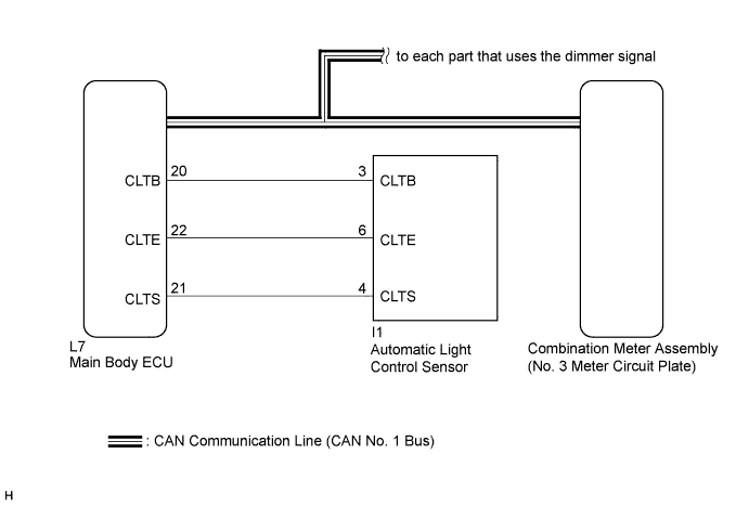
WIRING DIAGRAM
INSPECTION PROCEDURE
Tech Tips
The meter illumination can be customized by pressing the trip switch.
PROCEDURE
-
CHECK CAN COMMUNICATION SYSTEM
-
Check if a CAN communication DTC is output Click here.
Result Result Proceed to CAN communication DTC is not output. A CAN communication DTC is output. B
B 
GO TO CAN COMMUNICATION SYSTEM Click here
A 
-
-
CHECK DTC (LIGHT SENSOR CIRCUIT)
-
Check if DTC B1244 is output Click here.
Result Result Proceed to B1244 is not output. A B1244 is output. B
B
GO TO LIGHTING SYSTEM Click here
A
-
-
CHECK OPERATION (HEATER CONTROL PANEL)
-
Turn the power switch on (IG).
-
Turn the light control switch to the tail, head, or AUTO position.
-
Cover the automatic light control sensor.
-
Check the heater control panel illumination.
Result Result Proceed to Heater control panel illumination does not operate normally. A Heater control panel illumination operates normally. B Tech Tips
Both the heater control panel and the combination meter assembly illumination dim according to the dimmer signal. Therefore, when only the meter illumination is always dark, there may be a malfunction in the combination meter assembly.
B
REPLACE COMBINATION METER ASSEMBLY (NO. 3 METER CIRCUIT PLATE) Click here
A
-
-
CHECK OPERATION (AUTOMATIC LIGHT CONTROL SYSTEM)
-
Turn the power switch on (IG).
-
Turn the light control switch to the AUTO position.
-
Cover the automatic light control sensor.
-
Check the taillights and low beam headlights.
OK The taillights and low beam headlights come on. -
Uncover the automatic light control sensor.
-
Check the low beam headlights and taillights.
OK The taillights and low beam headlights go off. Result Result Proceed to Automatic light control system operates normally. A Automatic light control system does not operate normally. B
B
CHECK LIGHTING SETTING Click here
A
-
-
REPLACE MAIN BODY ECU
-
Replace the main body ECU with a new or a normal one Click here.
OK The operation of the combination meter assembly returns to normal. Tech Tips
The meter ECU (meter circuit plate No.3) controls the meter illumination based on an auto dimmer signal from the main body ECU. When the meter illumination is always dark (very dim), it may be due to the main body ECU sending an auto dimmer signal to the meter ECU (meter circuit plate No.3) because of a malfunction in the main body ECU.
NG
REPLACE COMBINATION METER ASSEMBLY (NO. 3 METER CIRCUIT PLATE) Click here
OK 
END
-