METER / GAUGE SYSTEM Odo/Trip Switch Malfunction
DESCRIPTION
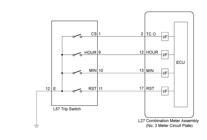
The meter ECU (meter circuit plate No.3) receives trip switch signals from the trip switch via the direct line in this circuit.
WIRING DIAGRAM
INSPECTION PROCEDURE
PROCEDURE
-
INSPECT TRIP SWITCH
-
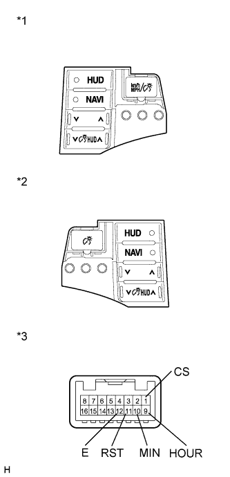
Text in Illustration *1 Trip Switch (for RHD) *2 Trip Switch (for LHD) *1 Component without harness connected
(Trip Switch)
Remove the trip switch.
-
Measure the resistance according to the value(s) in the table below.
Standard Resistance Tester Connection Condition Specified Condition 1 (CS) - 12 (E) Unit change switch pressed Below 1 Ω 1 (CS) - 12 (E) Unit change switch not pressed 10 kΩ or higher 9 (HOUR) - 12 (E) Hour adjust switch pressed Below 1 Ω 9 (HOUR) - 12 (E) Hour adjust switch not pressed 10 kΩ or higher 10 (MIN) - 12 (E) Minute adjust switch pressed Below 1 Ω 10 (MIN) - 12 (E) Minute adjust switch not pressed 10 kΩ or higher 11 (RST) - 12 (E) Set switch pressed Below 1 Ω 11 (RST) - 12 (E) Set switch not pressed 10 kΩ or higher
NG 
REPLACE TRIP SWITCH Click here
OK 
-
-
CHECK HARNESS AND CONNECTOR (NO. 3 METER CIRCUIT PLATE - TRIP SWITCH)
-
Disconnect the L27 and L57 connectors.
-
Measure the resistance according to the value(s) in the table below.
Standard Resistance Tester Connection Condition Specified Condition L27-2 (TC O) - L57-1 (CS) Always Below 1 Ω L27-2 (TC O) - Body ground Always 10 kΩ or higher L27-12 (HOUR) - L57-9 (HOUR) Always Below 1 Ω L27-12 (HOUR) - Body ground Always 10 kΩ or higher L27-13 (MIN) - L57-10 (MIN) Always Below 1 Ω L27-13 (MIN) - Body ground Always 10 kΩ or higher L27-17 (RST) - L57-11 (RST) Always Below 1 Ω L27-17 (RST) - Body ground Always 10 kΩ or higher
NG
REPAIR OR REPLACE HARNESS OR CONNECTOR
OK 
REPLACE COMBINATION METER ASSEMBLY (NO. 3 METER CIRCUIT PLATE) Click here
-