METER / GAUGE SYSTEM Speedometer Malfunction
DESCRIPTION
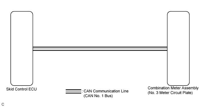
The meter ECU (No. 3 meter circuit plate) receives vehicle speed signals from the skid control ECU via the CAN communication system (CAN No. 1 Bus). The speed sensor detects the wheel speed and sends the appropriate signals to the skid control ECU. The skid control ECU supplies power to the vehicle speed sensor. The skid control ECU detects vehicle speed signals based on the pulses of the voltage.
Tech Tips
-
Factors that affect the indicated vehicle speed include tire size, tire inflation, and tire wear. The speed indicated on the speedometer has an allowable margin of error. This can be tested using a speedometer tester (calibrated chassis dynamometer). For details about testing and the margin of error, see the reference chart Click here.
-
If the vehicle speed sensor circuit has a malfunction, the skid control ECU stores the DTCs. Troubleshoot the Brake Control System Click here.
WIRING DIAGRAM
INSPECTION PROCEDURE
Note
If the vehicle speed is outside the allowable range when tested, perform the on-vehicle inspection Click here.
Tech Tips
Before starting the following inspection, check tire size and tire air pressure.
PROCEDURE
-
CHECK CAN COMMUNICATION SYSTEM
-
Check if a CAN communication DTC is output Click here.
Result Result Proceed to CAN communication DTC is not output. A CAN communication DTC is output. B
B 
GO TO CAN COMMUNICATION SYSTEM Click here
A 
-
-
PERFORM ACTIVE TEST USING INTELLIGENT TESTER (SPEED METER OPERATION)
-
Connect the intelligent tester to the DLC3.
-
Turn the power switch on (IG).
-
Turn the intelligent tester on.
-
Enter the following menus: Body / Combination Meter / Active Test.
-
Check the operation by referring to the table below.
Combination Meter Tester Display Test Part Control Range Diagnostic Note Speed Meter Operation Speedometer 0, 40, 80, 120 mph*1 Confirm that the vehicle is stopped with the engine idling 0, 40, 80, 120, 160, 200, 240 km/h*2
-
*1: for models with mph unit
-
*2: for models with km/h unit
OK Speedometer indication is normal. -
NG
REPLACE COMBINATION METER ASSEMBLY (NO. 3 METER CIRCUIT PLATE) Click here
OK
-
-
CHECK BRAKE CONTROL SYSTEM
-
Check if the brake control system output the DTC Click here.
Result Result Proceed to The DTC is not output. A The DTC is output. B
B
GO TO BRAKE CONTROL SYSTEM Click here
A
-
-
READ VALUE USING INTELLIGENT TESTER (FR/FL/RR/RL WHEEL SPEED, VEHICLE SPEED METER)
-
Connect the intelligent tester to the DLC3.
-
Turn the power switch on (IG).
-
Turn the intelligent tester on.
-
Enter the following menus:
-
for ABS/VSC/TRAC: Chassis / ABS/VSC/TRC / Data List.
-
for Combination Meter: Body Electrical / Combination Meter / Data List.
-
-
Check the values by referring to the table below.
ABS/VSC/TRC Tester Display Measurement Item/Range Normal Condition Diagnostic Note FR Wheel Speed Vehicle speed/Min.: 0 km/h (0 mph), Max.: 326 km/h (203 mph) Almost the same as actual vehicle speed (Speedometer tester) - FL Wheel Speed Vehicle speed/Min.: 0 km/h (0 mph), Max.: 326 km/h (203 mph) Almost the same as actual vehicle speed (Speedometer tester) - RR Wheel Speed Vehicle speed/Min.: 0 km/h (0 mph), Max.: 326 km/h (203 mph) Almost the same as actual vehicle speed (Speedometer tester) - RL Wheel Speed Vehicle speed/Min.: 0 km/h (0 mph), Max.: 326 km/h (203 mph) Almost the same as actual vehicle speed (Speedometer tester) - Combination Meter Tester Display Measurement Item/Range Normal Condition Diagnostic Note Vehicle Speed Meter Vehicle speed/Min.: 0 mph (0 km/h), Max.: 199 km/h (124 mph) Almost the same as actual vehicle speed (Speedometer tester) - OK When the Data List values of the ECUs match, an internal malfunction of the combination meter assembly is suspected. NG When the Data List values of the ECUs do not match, a signal output error of the skid control ECU or an internal malfunction of the combination meter assembly is suspected.
NG 
REPLACE COMBINATION METER ASSEMBLY (METER CIRCUIT PLATE) Click here
OK 
GO TO BRAKE CONTROL SYSTEM Click here
-
-
REPLACE COMBINATION METER ASSEMBLY (METER CIRCUIT PLATE)
-
Replace the combination meter assembly (meter circuit plate) with a new or a known good one Click here.
OK The operation of the speedometer returns to normal.
NG
REPLACE COMBINATION METER ASSEMBLY (NO. 4 METER CIRCUIT PLATE) Click here
OK
END
-
-
REPLACE COMBINATION METER ASSEMBLY (NO. 4 METER CIRCUIT PLATE)
-
Replace the combination meter assembly (No. 4 meter circuit plate) with a new or a known good one Click here.
OK The operation of the speedometer returns to normal.
NG
REPLACE COMBINATION METER ASSEMBLY (NO. 3 METER CIRCUIT PLATE) Click here
OK
END
-
-
REPLACE COMBINATION METER ASSEMBLY (NO. 3 METER CIRCUIT PLATE)
-
Replace the combination meter assembly (No. 3 meter circuit plate) with a new or a known good one Click here.
OK The operation of the speedometer returns to normal. Result Result Proceed to OK A NG (for LHD) B NG (for RHD) C
B
REPLACE SKID CONTROL ECU Click here
C
REPLACE SKID CONTROL ECU Click here
A
END
-