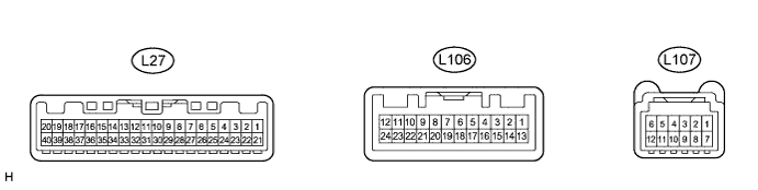
METER / GAUGE SYSTEM TERMINALS OF ECU

-
COMBINATION METER ASSEMBLY
-
Measure the voltage and resistance according to the value(s) in the table below.
Terminal No. (Symbol) Wiring Color Terminal Description Condition Specified Condition L27-2 (TC O)*1 - Body ground G - Body ground Trip switch signal (Unit change switch) Unit change switch not pressed 11 to 14 V Unit change switch pressed Below 1 V L27-2 (TC O)*2 - Body ground G - Body ground Trip switch signal (Tail cancel switch) Tail cancel switch not pressed 11 to 14 V Tail cancel switch pressed Below 1 V L27-3 (TIRE)*3 - Body ground G - Body ground Tire pressure warning light signal Power switch on (IG), tire pressure warning light off 3.2 V or higher Power switch on (IG), tire pressure warning light on 0.9 to 3.2 V L27-5 (S) - Body ground R - Body ground Oil pressure switch signal Power switch on (IG), oil pressure warning display off Below 1 V Power switch on (IG), oil pressure warning display comes on 11 to 14 V L27-6 (LVWG) - Body ground L - Body ground Headlight leveling indicator light signal Power switch on (IG), headlight leveling indicator light off 11 to 14 V Power switch on (IG), headlight leveling indicator light blinks Below 1 V ←→ 11 to 14 V L27-7 (+S) - Body ground V - Body ground Speed signal for other systems (Output) Power switch on (IG), wheel being rotated Pulse generation
(See waveform 1)
L27-8 (SI) - Body ground V - Body ground Speed signal (Input) Power switch on (IG), wheel being rotated Pulse generation
(See waveform 1)
L27-9 (E2) - Body ground G - Body ground Ground (Water temperature sensor ground) Always Below 1 Ω L27-10 (CANH) - Body ground P - Body ground CAN communication signal Power switch off 200 Ω or higher L27-11 (CANL) - Body ground W - Body ground CAN communication signal Power switch off 200 Ω or higher L27-12 (HOUR) - Body ground B - Body ground Trip switch signal (Hour adjust switch) Hour adjust switch not pressed 11 to 14 V Hour adjust switch pressed Below 1 V L27-13 (MIN) - Body ground B - Body ground Trip switch signal (Minute adjust switch) Minute adjust switch not pressed 11 to 14 V Minute adjust switch pressed Below 1 V L27-14 (L) - Body ground B - Body ground Fuel level signal Power switch on (IG), fuel level warning light OFF Below 1 V Power switch on (IG), fuel level warning light ON 3 to 7 V L27-15 (ES2) - Body ground W - Body ground Ground (Fuel ground) Always Below 1 Ω L27-16 (TWS3) - Body ground B - Body ground Water temperature sensor signal Power switch on (IG), engine coolant temperature below 113°C (235°F) 0.2 to 4.8 V Power switch on (IG), engine coolant temperature below 120°C (248°F) or more Below 0.15 V L27-17 (RST) - Body ground R - Body ground Trip switch signal (Set switch) Set switch not pressed 11 to 14 V Set switch pressed Below 1 V L27-18 (B) - Body ground R - Body ground Battery Power switch off 11 to 14 V L27-19 (IG+) - Body ground L - Body ground Power switch signal Power switch off Below 1 V Power switch on (IG) 11 to 14 V L27-20 (IG2) - Body ground G - Body ground Power switch signal Power switch off Below 1 V Power switch on (IG) 11 to 14 V L27-21 (PBLT) - Body ground Y - Body ground Front passenger side seat belt warning light signal Power switch on (IG), front passenger side seat belt warning light off 11 to 14 V Power switch on (IG), front passenger side seat belt warning light blinks Below 1 V ←→ 11 to 14 V L27-22 (LP) - Body ground B - Body ground Security indicator light signal Power switch on (IG), security indicator light off Below 2 V Security indicator light blinks Pulse generation L27-24 (SW) - Body ground P - Body ground Front passenger side seat belt buckle switch signal Power switch on (IG), sit on the front passenger seat, and front passenger side seat belt unfastened Below 1 V Power switch on (IG), sit on the front passenger seat, and front passenger side seat belt fastened 11 to 14 V L27-25 (EFI) - Body ground LG - Body ground MIL (Check engine warning light) signal Power switch on (IG), MIL (Check engine warning light) off 11 to 14 V Power switch on (IG), MIL (Check engine warning light) comes on Below 1 V L27-26 (B) - Body ground Y - Body ground Turn LH indicator light signal Power switch on (IG), turn LH indicator light off 11 to 14 V Power switch on (IG), turn LH indicator light blinks Below 1 V ←→ 11 to 14 V L27-27 (B) - Body ground G - Body ground Turn RH indicator light signal Power switch on (IG), turn RH indicator light off 11 to 14 V Power switch on (IG), turn RH indicator light blinks Below 1 V ←→ 11 to 14 V L27-29 (STRG) - Body ground G - Body ground Steering pad switch signal Always Pulse generation L27-30 (ES) - Body ground BR - Body ground Ground (Signal ground) Always Below 1 Ω L106-1 (12V) - Body ground B - Body ground Power switch signal Power switch off 11 to 14 V L106-4 (GND) - Body ground W - Body ground Ground Always Below 1 Ω L106-5 (BKR) - Body ground P - Body ground Headup display illumination signal Power switch on (IG) Pulse generation L106-6 (LAT) - Body ground R - Body ground Headup display dot illumination timing signal Power switch on (IG) Pulse generation L106-7 (CLKH) - Body ground R - Body ground Clock signal Always Pulse generation L106-8 (CLKL) - Body ground G - Body ground Clock signal Always Pulse generation L106-9 (SIH) - Body ground G - Body ground Headup display dot signal Power switch on (IG) Pulse generation L106-10 (SIL) - Body ground R - Body ground Headup display dot signal Power switch on (IG) Pulse generation L106-11 (WE) - Body ground L - Body ground Headup display dot illumination signal Power switch on (IG), headup display illuminated Pulse generation L106-14 (STP1) - Body ground V - Body ground Stepper motor signal Power switch on (IG) Pulse generation L106-15 (STP2) - Body ground LG - Body ground Stepper motor signal Power switch on (IG) Pulse generation L106-16 (STP3) - Body ground B - Body ground Stepper motor signal Power switch on (IG) Pulse generation L106-17 (STP4) - Body ground W - Body ground Stepper motor signal Power switch on (IG) Pulse generation L107-1 (NVSW) - L107-2 (E) Y - BE Navigation system display select switch signal Turn the power switch on (IG), navigation system display select switch not pressed Below 1 V Turn the power switch on (IG), navigation system display select switch pressed 11 to 14 V L107-2 (E) - Body ground BE - Body ground Ground Always Below 1 Ω L107-3 (HUDI) - Body ground W - Body ground Headup display indicator light signal Turn the power switch on (IG), headup display indicator light goes off Below 1 V Turn the power switch on (IG), headup display indicator light comes on 11 to 14 V L107-4 (HUDD) - L107-2 (E) R - BE Headup display position down switch signal Turn the power switch on (IG), headup display position down switch not pressed Below 1 V Turn the power switch on (IG), headup display position down switch pressed 11 to 14 V L107-7 (HUDU) - L107-2 (E) P - BE Headup display position up switch signal Turn the power switch on (IG), headup display position down switch not pressed Below 1 V Turn the power switch on (IG), headup display position down switch pressed 11 to 14 V L107-8 (HUDO) - L107-2 (E) B - BE Headup display mode select switch signal Turn the power switch on (IG), headup display mode select switch not pressed Below 1 V Turn the power switch on (IG), headup display mode select switch pressed 11 to 14 V L107-9 (IIND) - Body ground BE - Body ground Navigation system indicator light signal Turn the power switch on (IG), navigation system indicator light goes off Below 1 V Turn the power switch on (IG), navigation system indicator light comes on 11 to 14 V
-
*1: w/ Unit Change Switch
-
*2: w/o Unit Change Switch
-
*3: w/ Tire Pressure Warning System
-
-
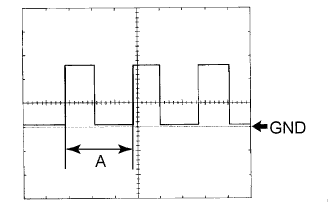
Waveform 1 (Reference):
Item Condition Tool setting 5 V/DIV., 20 ms./DIV. Vehicle condition Power switch on (IG), wheel being rotated Tech Tips
When the system is functioning normally, one wheel revolution generates 4 pulses. As the vehicle speed increases, the width indicated by (A) in the illustration narrows.
-
-
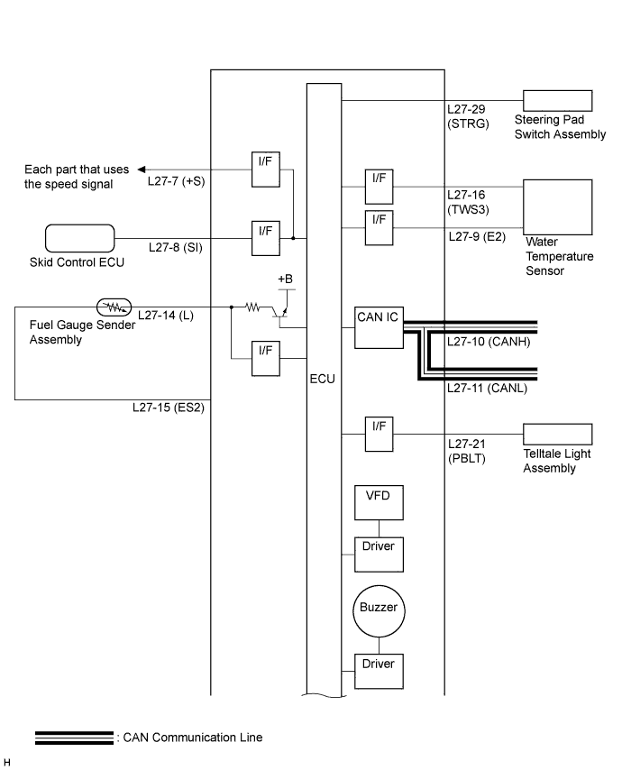
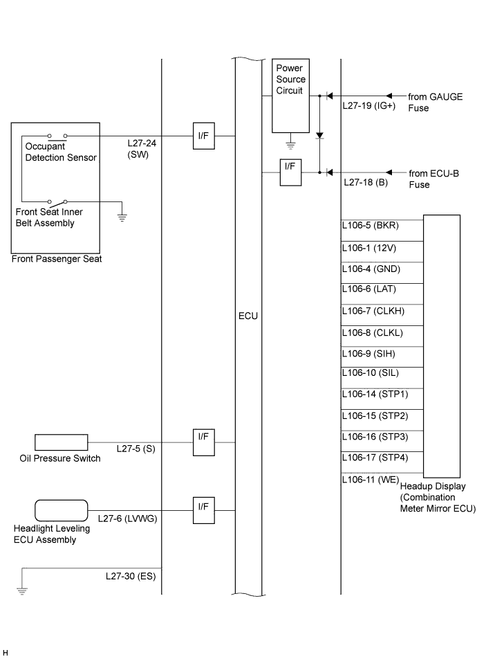
COMBINATION METER ASSEMBLY INNER CIRCUIT
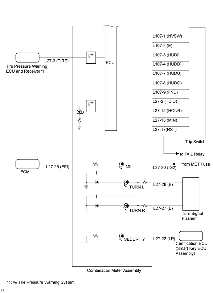
Terminal No. (Symbol) Wire Harness Side L27 1 - 2 (TC O) Trip Switch 3 (TIRE) Tire Pressure Warning ECU and Receiver*3 4 - 5 (S) Oil Pressure Switch 6 (LVWG) Headlight Leveling ECU Assembly 7 (+S) Each part that uses the speed signal 8 (SI) Skid Control ECU 9 (E2) Ground (Water Temperature Sensor Ground) 10 (CANH) CAN Communication Line 11 (CANL) CAN Communication Line 12 (HOUR) Trip Switch 13 (MIN) Trip Switch 14 (L) Fuel Sender Gauge Assembly 15 (ES2) Fuel Sender Gauge Assembly 16 (TWS3) Water Temperature Sensor 17 (RST) Trip Switch 18 (B) ECU-B Fuse 19 (IG+) GAUGE Fuse 20 (IG2) MET Fuse 21 (PBLT) Telltale Light Assembly 22 (LP) Certification ECU (Smart Key ECU Assembly) 23 - 24 (SW) Front Seat Inner Belt Assembly RH*1 or Front Seat Inner Belt Assembly LH*2 25 (EFI) ECM 26 (B) Turn Signal Flasher 27 (B) Turn Signal Flasher 28 - 29 (STRG) Steering Pad Switch Assembly 30 (ES) Ground 31 - 32 - 33 - 34 - 35 - 36 - 37 - 38 - 39 - 40 -
-
*1: for LHD
-
*2: for RHD
-
*3: w/ Tire Pressure Warning System
Terminal No. (Symbol) Wire Harness Side L106 1 (12V) Headup Display 2 - 3 - 4 (GND) Ground 5 (BKR) Headup Display (Combination Meter Mirror ECU) 6 (LAT) Headup Display (Combination Meter Mirror ECU) 7 (CLKH) Headup Display (Combination Meter Mirror ECU) 8 (CLKL) Headup Display (Combination Meter Mirror ECU) 9 (SIH) Headup Display (Combination Meter Mirror ECU) 10 (SIL) Headup Display (Combination Meter Mirror ECU) 11 (WE) Headup Display (Combination Meter Mirror ECU) 12 - 13 - 14 (STP1) Headup Display (Combination Meter Mirror ECU) 15 (STP2) Headup Display (Combination Meter Mirror ECU) 16 (STP3) Headup Display (Combination Meter Mirror ECU) 17 (STP4) Headup Display (Combination Meter Mirror ECU) 18 - 19 - 20 - 21 - 22 - 23 - 24 - L107 1 (NVSW) Trip Switch 2 (E) Trip Switch 3 (HUDI) Trip Switch 4 (HUDD) Trip Switch 5 - 6 - 7 (HUDU) Trip Switch 8 (HUDO) Trip Switch 9 (IIND) Trip Switch 10 - 11 - 12 - 13 - 14 - 15 - 16 - -