LIGHTING SYSTEM Footwell Light Circuit
DESCRIPTION
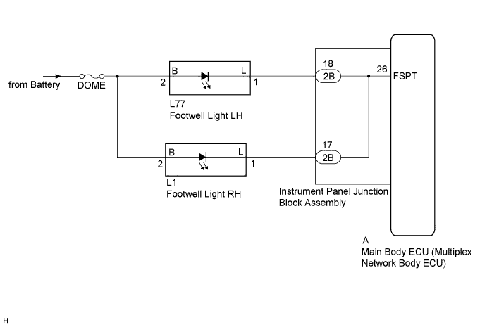
The main body ECU (multiplex network ECU) control the footwell lights.
WIRING DIAGRAM
INSPECTION PROCEDURE
PROCEDURE
-
PERFORM ACTIVE TEST USING INTELLIGENT TESTER
-
Connect the intelligent tester to the DLC3.
-
Turn the power switch on (IG).
-
Turn the intelligent tester on.
-
Enter the following menus: Body / Main Body / Active Test.
-
Check that the foot lights come on.
Main Body Tester Display Test Part Control Range Diagnostic Note Step Light Operation Footwell lights ON/OFF - OK Footwell lights come on.
NG 
CHECK HARNESS AND CONNECTOR (MAIN BODY ECU - BATTERY) Click here
OK 
PROCEED TO NEXT SUSPECTED AREA SHOWN IN PROBLEM SYMPTOMS TABLE Click here
-
-
CHECK HARNESS AND CONNECTOR (MAIN BODY ECU - BATTERY)
-
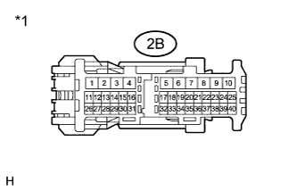
Text in Illustration *1 Front view of wire harness connector
(to Instrument Panel Junction Block Assembly)
Disconnect the 2B instrument panel junction block assembly connector.
-
Measure the voltage according to the value(s) in the table below.
Standard Voltage Tester Connection Condition Specified Condition 2B-17 - Body ground Always 11 to 14 V 2B-18 - Body ground Always 11 to 14 V
NG 
REPAIR OR REPLACE HARNESS OR CONNECTOR
OK 
-
-
INSPECT INSTRUMENT PANEL JUNCTION BLOCK ASSEMBLY
-
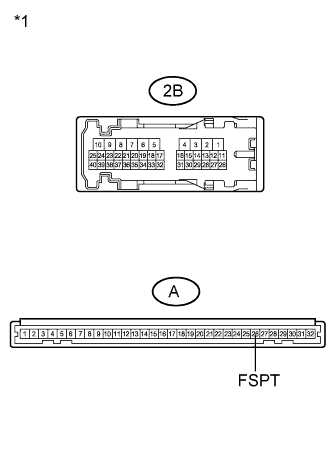
Text in Illustration *1 Component without harness connected
(Instrument Panel Junction Block Assembly)
Remove the instrument panel junction block assembly.
-
Measure the resistance according to the value(s) in the table below.
Standard Resistance Tester Connection Condition Specified Condition 2B-17 - A-26 (FSPT) Always Below 1 Ω 2B-18 - A-26 (FSPT) Always Below 1 Ω A-26 - Body ground Always 10 kΩ or higher
NG
REPLACE INSTRUMENT PANEL JUNCTION BLOCK ASSEMBLY
OK
REPLACE MAIN BODY ECU (MULTIPLEX NETWORK BODY ECU) Click here
-