LIGHTING SYSTEM TERMINALS OF ECU

-
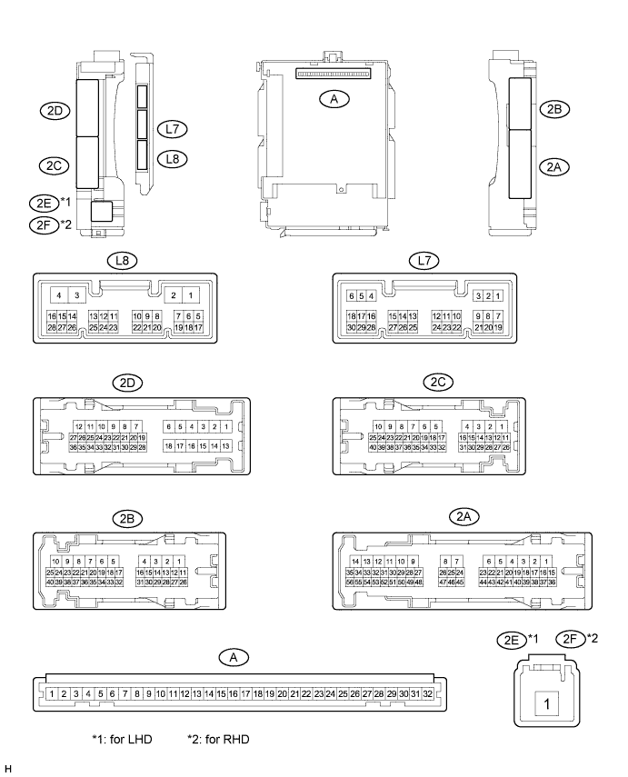
CHECK INSTRUMENT PANEL JUNCTION BLOCK ASSEMBLY AND MAIN BODY ECU (MULTIPLEX NETWORK BODY ECU) (w/ LED Headlight System, w/ Remote Air Conditioning System or w/ Theft Deterrent System)
-
Disconnect the 2A, 2B, 2C, 2E*1, 2F*2 and L8 instrument panel junction block assembly and main body ECU (multiplex network body ECU) connectors.
-
Measure the voltage according to the value(s) in the table below.
Terminal No. (Symbol) Wiring Color Terminal Description Condition Specified Condition 2A-43 - Body ground G - Body ground ACC power supply Power switch on (ACC) 11 to 14 V Power switch off Below 1 V 2B-25 - Body ground B - Body ground IG power supply Power switch on (IG) 11 to 14 V Power switch off Below 1 V 2C-18 (BECU) - Body ground Y - Body ground Battery power supply Always 11 to 14 V 2E-1*1 - Body ground W - Body ground Battery power supply Always 11 to 14 V 2F-1*2 - Body ground W - Body ground Battery power supply Always 11 to 14 V If the result is not as specified, there may be a malfunction in the wire harness.
-
Measure the resistance according to the value(s) in the table below.
Terminal No. (Symbol) Wiring Color Terminal Description Condition Specified Condition 2B-6 (GND1) - Body ground W-B - Body ground Ground Always Below 1 Ω L8-3 (GND2) - Body ground W-B - Body ground Ground Always Below 1 Ω If the result is not as specified, there may be a malfunction in the wire harness.
-
Reconnect the 2A, 2B, 2C, 2E*1, 2F*2 and L8 instrument panel junction block assembly and main body ECU (multiplex network body ECU) connectors.
-
Measure the voltage and check for pulses according to the value(s) in the table below.
Terminal No. (Symbol) Wiring Color Terminal Description Condition Specified Condition 2A-52 (ILE) - Body ground L - Body ground Interior lights drive output Interior lights off 11 to 14 V Interior lights on Below 1 V 2B-17 (FSPT) - Body ground L - Body ground Front passenger footwell light drive output Front passenger footwell light off 11 to 14 V Front passenger footwell light on Below 1 V 2B-18 (FSPT) - Body ground L - Body ground Driver footwell light drive output Driver footwell light off 11 to 14 V Driver footwell light on Below 1 V 2B-29 (LSR) - Body ground GR - Body ground Rear door unlock detection switch RH input Rear door RH and LH locked Pulse generation Rear door RH or LH unlocked Below 1 V 2D-25 (LSR) - Body ground GR - Body ground Rear door unlock detection switch LH input Rear door LH and RH locked Pulse generation Rear door LH or RH unlocked Below 1 V 2D-35 (FLCY) - Body ground V*1 - Body ground
BR*2 - Body ground
Front door courtesy light switch LH input Front door LH open Below 1 V Front door LH closed 11 to 14 V 2D-36 (FRCY) - Body ground BR*1 - Body ground
V*2 - Body ground
Front door courtesy light switch RH input Front door RH open Below 1 V Front door RH closed 11 to 14 V L7-6 (LRCY) - Body ground G - Body ground Rear door courtesy light switch RH or LH input Rear door RH or LH open Below 1 V Rear door RH and LH closed Pulse generation L7-7 (LSFL) - Body ground GR - Body ground Front door unlock detection switch LH input Front door LH locked Pulse generation Front door LH unlocked Below 1 V L7-18 (LSFR) - Body ground LG - Body ground Front door unlock detection RH switch input Front door RH locked Pulse generation Front door RH unlocked Below 1 V L7-19 (BCTY) - Body ground L - Body ground Back door courtesy light switch input Back door open Below 1 V Back door closed and luggage compartment light switch off Pulse generation Back door closed and luggage compartment light switch on 11 to 14 V Tech Tips
*1: for LHD
*2: for RHD
If the result is not as specified, the main body ECU (multiplex network body ECU) or instrument panel junction block assembly may have a malfunction.
-
-
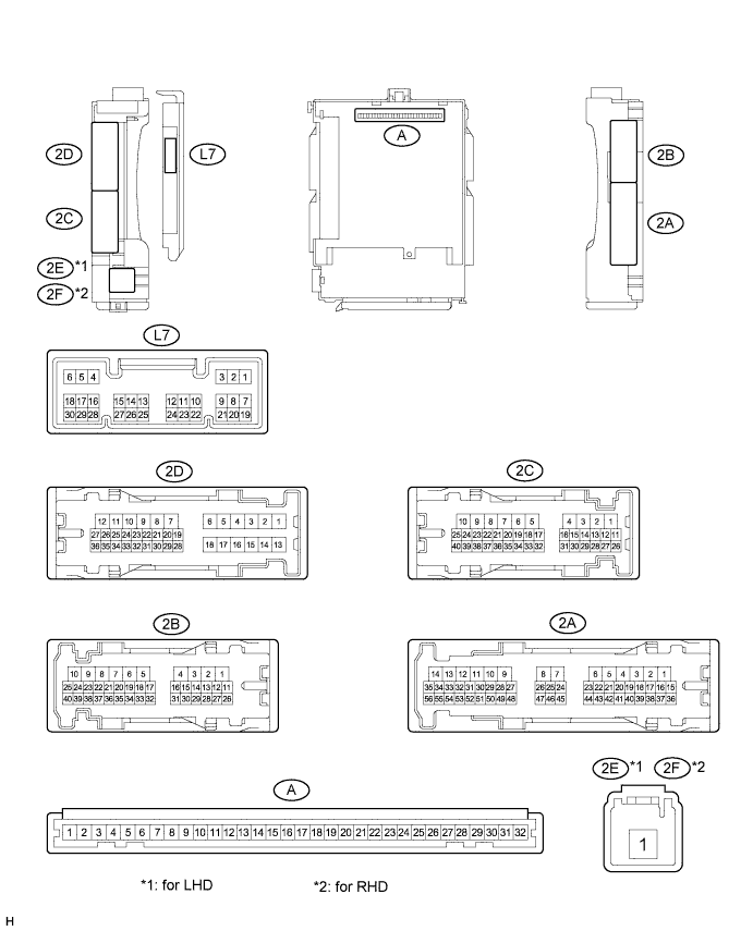
CHECK INSTRUMENT PANEL JUNCTION BLOCK ASSEMBLY AND MAIN BODY ECU (MULTIPLEX NETWORK BODY ECU) (w/o LED Headlight System, w/o remote Air Conditioning System and w/o Theft Deterrent System)
-
Disconnect the 2A, 2B, 2C, 2E*1 and 2F*2 instrument panel junction block assembly and main body ECU (multiplex network body ECU) connectors.
-
Measure the voltage according to the value(s) in the table below.
Terminal No. (Symbol) Wiring Color Terminal Description Condition Specified Condition 2A-43 - Body ground G - Body ground ACC power supply Power switch on (ACC) 11 to 14 V Power switch off Below 1 V 2B-25 - Body ground B - Body ground IG power supply Power switch on (IG) 11 to 14 V Power switch off Below 1 V 2C-18 (BECU) - Body ground Y - Body ground Battery power supply Always 11 to 14 V 2E-1*1 - Body ground W - Body ground Battery power supply Always 11 to 14 V 2F-1*2 - Body ground W - Body ground Battery power supply Always 11 to 14 V If the result is not as specified, there may be a malfunction in the wire harness.
-
Measure the resistance according to the value(s) in the table below.
Terminal No. (Symbol) Wiring Color Terminal Description Condition Specified Condition 2B-6 (GND1) - Body ground W-B - Body ground Ground Always Below 1 Ω If the result is not as specified, there may be a malfunction in the wire harness.
-
Reconnect the 2A, 2B, 2C, 2E*1 and 2F*2 instrument panel junction block assembly and main body ECU (multiplex network body ECU) connectors.
-
Measure the voltage and check for pulses according to the value(s) in the table below.
Terminal No. (Symbol) Wiring Color Terminal Description Condition Specified Condition 2A-52 (ILE) - Body ground L - Body ground Interior lights drive output Interior lights off 11 to 14 V Interior lights on Below 1 V 2B-17 (FSPT) - Body ground L - Body ground Front passenger footwell light drive output Front passenger footwell light off 11 to 14 V Front passenger footwell light on Below 1 V 2B-18 (FSPT) - Body ground L - Body ground Driver footwell light drive output Driver footwell light off 11 to 14 V Driver footwell light on Below 1 V 2B-29 (LSR) - Body ground GR - Body ground Rear door unlock detection switch RH input Rear door RH and LH locked Pulse generation Rear door RH or LH unlocked Below 1 V 2D-25 (LSR) - Body ground GR - Body ground Rear door unlock detection switch LH input Rear door LH and RH locked Pulse generation Rear door LH or RH unlocked Below 1 V 2D-35 (FLCY) - Body ground V*1 - Body ground
BR*2 - Body ground
Front door courtesy light switch LH input Front door LH open Below 1 V Front door LH closed 11 to 14 V 2D-36 (FRCY) - Body ground BR*1 - Body ground
V*2 - Body ground
Front door courtesy light switch RH input Front door RH open Below 1 V Front door RH closed 11 to 14 V L7-6 (LRCY) - Body ground G - Body ground Rear door courtesy light switch RH or LH input Rear door RH or LH open Below 1 V Rear door RH and LH closed Pulse generation L7-7 (LSFL) - Body ground GR - Body ground Front door unlock detection switch LH input Front door LH locked Pulse generation Front door LH unlocked Below 1 V L7-18 (LSFR) - Body ground LG - Body ground Front door unlock detection RH switch input Front door RH locked Pulse generation Front door RH unlocked Below 1 V L7-19 (BCTY) - Body ground L - Body ground Back door courtesy light switch input Back door open Below 1 V Back door closed and luggage compartment light switch off Pulse generation Back door closed and luggage compartment light switch on 11 to 14 V Tech Tips
*1: for LHD
*2: for RHD
If the result is not as specified, the main body ECU (multiplex network body ECU) or instrument panel junction block assembly may have a malfunction.
-
-
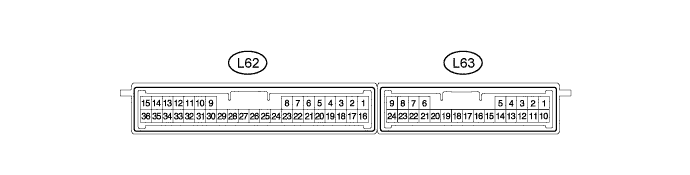
CHECK CERTIFICATION ECU (SMART KEY ECU ASSEMBLY)
-
Disconnect the L62 certification ECU (smart key ECU assembly) connector.
-
Measure the voltage according to the value(s) in the table below.
Terminal No. (Symbol) Wiring Color Terminal Description Condition Specified Condition L62-1 (+B) - Body ground B - Body ground +B power supply Always 11 to 14 V If the result is not as specified, there may be a malfunction in the wire harness.
-
Measure the resistance according to the value(s) in the table below.
Terminal No. (Symbol) Wiring Color Terminal Description Condition Specified Condition L62-15 (E) - Body ground W-B - Body ground Ground Always Below 1 Ω If the result is not as specified, there may be a malfunction in the wire harness.
-
Reconnect the L62 certification ECU (smart key ECU assembly) connector.
-
Measure the voltage and check for pulses according to the value(s) in the table below.
Terminal No. (Symbol) Wiring Color Terminal Description Condition Specified Condition L62-11 (SWIL) - Body ground G - Body ground Power switch illumination drive output Power switch illumination on 11 to 14 V or pulse generation Power switch illumination off Below 1 V If the result is not as specified, the certification ECU (smart key ECU assembly) may have a malfunction.
-