BLOCKING SYSTEM TERMINALS OF ECU

-
CHECK TELEPHONE TRANSCEIVER ASSEMBLY
-
Disconnect the L156 telephone transceiver assembly connector.

-
Measure the resistance and voltage according to the value(s) in the table below.
Tester Connection Wiring Color Terminal Description Condition Specified Condition L156-6 (IG2) - L156-9 (E) L - BR Ignition power supply Power switch on (IG) 9 to 16 V L156-12 (+B) - L156-9 (E) SB - BR +B power supply Power switch off 9 to 16 V L156-9 (E) - Body ground BR - Body ground Ground Always Below 1 Ω
-
If the result is not as specified, there may be a malfunction on the wire harness side.
-
-
Reconnect the L156 telephone transceiver assembly connector.
-
Measure the voltage according to the value(s) in the table below.
Tester Connection Wiring Color Terminal Description Condition Specified Condition L156-1 (BLK1) - L156-9 (E) L - BR ID code box (immobiliser code ECU) communication input Power switch off 11 to 14 V L156-1 (BLK1) - L156-9 (E) L - BR ID code box (immobiliser code ECU) communication input Within 3 seconds of power switch on (READY), or within 3 seconds of power switch turned on (IG) after auxiliary battery cable disconnected and reconnected Pulse generation
(See waveform 1)
L156-2 (BLK4) - L156-9 (E) R - BR ID code box (immobiliser code ECU) communication output Power switch off Below 1 V L156-2 (BLK4) - L156-9 (E) R - BR ID code box (immobiliser code ECU) communication output Within 3 seconds of power switch on (READY), or within 3 seconds of power switch turned on (IG) after auxiliary battery cable disconnected and reconnected Pulse generation
(See waveform 2)
L156-7 (BLK2) - L156-9 (E) L -BR Power management control ECU (HV CPU) communication output Power switch off Below 1 V L156-7 (BLK2) - L156-9 (E) L - BR Power management control ECU (HV CPU) communication output Within 3 seconds of power switch on (READY), or within 3 seconds of power switch turned on (IG) after auxiliary battery cable disconnected and reconnected Pulse generation
(See waveform 1)
L156-8 (BLK3) - L156-9 (E) R - BR Power management control ECU (HV CPU) communication input Power switch off Below 1 V L156-8 (BLK3) - L156-9 (E) R - BR Power management control ECU (HV CPU) communication input Within 3 seconds of power switch on (READY), or within 3 seconds of power switch turned on (IG) after auxiliary battery cable disconnected and reconnected Pulse generation
(See waveform 2)
-
If the result is not as specified, the telephone transceiver assembly may have a malfunction.
-
-
Inspect using an oscilloscope.
Note
The waveform shown in the illustration is an example for reference only. Noise, chattering, etc. are not shown.
-
Waveform 1 (Reference)
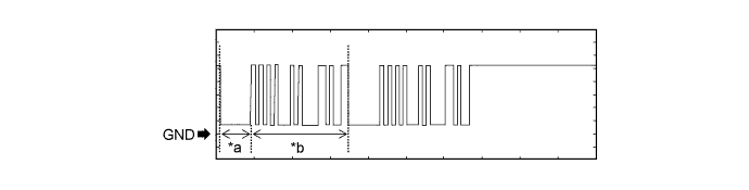
Text in Illustration *a Approximately 160 ms *b Approximately 510 ms Measurement Condition Item Content Tester Connection
-
L156-1 (BLK1) - L156-9 (E)
-
L156-7 (BLK2) - L156-9 (E)
Tool Setting 2 V/DIV., 500 ms./DIV. Condition Within 3 seconds of power switch on (READY), or within 3 seconds of power switch turned on (IG) after auxiliary battery cable disconnected and reconnected -
-
Waveform 2 (Reference)
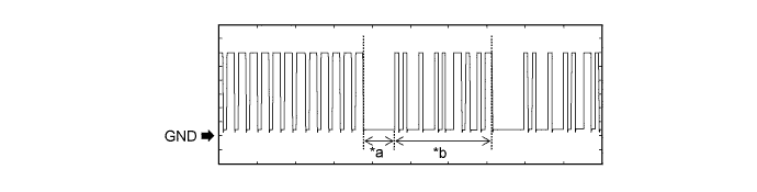
Text in Illustration *a Approximately 160 ms *b Approximately 510 ms Measurement Condition Item Content Tester Connection
-
L156-2 (BLK4) - L156-9 (E)
-
L156-8 (BLK3) - L156-9 (E)
Tool Setting 2 V/DIV., 500 ms./DIV. Condition Within 3 seconds of power switch on (READY), or within 3 seconds of power switch turned on (IG) after auxiliary battery cable disconnected and reconnected -
-
-
-
CHECK ID CODE BOX (IMMOBILISER CODE ECU)
-
Disconnect the L10 ID code box (immobiliser code ECU) connector.

-
Measure the resistance and voltage according to the value(s) in the table below.
Tester Connection Wiring Color Terminal Description Condition Specified Condition L10-1 (+B) - L10-8 (GND) B - W-B +B power supply Power switch off 11 to 14 V L10-8 (GND) - Body ground W-B - Body ground Ground Always Below 1 Ω
-
If the result is not as specified, there may be a malfunction in the wire harness.
-
-
Reconnect the L10 ID code box (immobiliser code ECU) connector.
-
Measure the voltage according to the value(s) in the table below.
Tester Connection Wiring Color Terminal Description Condition Specified Condition L10-5 (EFII) - L10-8 (GND) L - W-B Power management control ECU (HV CPU) input signal Power switch off 11 to 14 V L10-5 (EFII) - L10-8 (GND) L - W-B Power management control ECU (HV CPU) input signal Within 3 seconds after power switch on (READY), or within 3 seconds after power switch first turned on (IG) after auxiliary battery disconnected and connected Pulse generation
(See waveform 1)
L10-6 (EFIO) - L10-8 (GND) R - W-B Power management control ECU (HV CPU) output signal Power switch off Below 1 V L10-6 (EFIO) - L10-8 (GND) R - W-B Power management control ECU (HV CPU) output signal Power switch on (IG) Pulse generation
(See waveform 2)
-
If the result is not as specified, the ID code box (immobiliser code ECU) may have a malfunction.
-
-
Inspect using an oscilloscope.
-
Waveform 1 (Reference)
Text in Illustration *a Approximately 160 ms *b Approximately 510 ms Measurement Condition Item Content Tester Connection L10-5 (EFII) - L10-8 (GND) Tool Setting 2 V/DIV., 500 ms./DIV. Condition Within 3 seconds after power switch on (READY), or within 3 seconds after power switch first turned on (IG) after auxiliary battery disconnected and connected -
Waveform 2 (Reference)
Text in Illustration *a Approximately 160 ms *b Approximately 510 ms Measurement Condition Item Content Tester Connection L10-6 (EFIO) - L10-8 (GND) Tool Setting 2 V/DIV., 500 ms./DIV. Condition Power switch on (IG)
-
-
-
CHECK POWER MANAGEMENT CONTROL ECU (HV CPU)
-
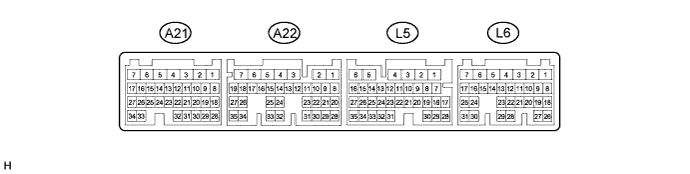
Disconnect the L5 power management control ECU (HV CPU) connector.
-
Measure the resistance according to the value(s) in the table below.
Tech Tips
Measure the values on the wire harness side with the connector disconnected.
Tester Connection Wiring Color Terminal Description Condition Specified Condition L5-6 (E1) - Body ground BR - Body ground Ground Always Below 1 Ω If the result is not as specified, there may be a malfunction in the wire harness.
-
Reconnect the L5 power management control ECU (HV CPU) connector.
-
Measure the voltage according to the value(s) in the table below.
Tester Connection Wiring Color Terminal Description Condition Specified Condition L6-20 (IMO) - L5-6 (E1) L - BR ID code box (immobiliser code ECU) input signal Power switch off 11 to 14 V L6-20 (IMO) - L5-6 (E1) L - BR ID code box (immobiliser code ECU) input signal Within 3 seconds after power switch on (READY), or within 3 seconds after power switch first turned on (IG) after auxiliary battery disconnected and connected Pulse generation
(See waveform 1)
L6-21 (IMI) - L5-6 (E1) R - BR ID code box (immobiliser code ECU) output signal Power switch off Below 1 V L6-21 (IMI) - L5-6 (E1) R - BR ID code box (immobiliser code ECU) output signal Power switch on (IG) Pulse generation
(See waveform 2)
If the result is not as specified, the power management control ECU (HV CPU) may have a malfunction.
-
Waveform:
-
Waveform 1 (Reference)
Text in Illustration *a Approximately 160 ms *b Approximately 510 ms Measurement Condition Item Content Tester Connection L6-20 (IMO) - L5-6 (E1) Tool Setting 2 V/DIV., 500 ms./DIV. Condition Within 3 seconds after power switch on (READY), or within 3 seconds after power switch first turned on (IG) after auxiliary battery disconnected and connected -
Waveform 2 (Reference)
Text in Illustration *a Approximately 160 ms *b Approximately 510 ms Measurement Condition Item Content Tester Connection L6-21 (IMI) - L5-6 (E1) Tool Setting 2 V/DIV., 500 ms./DIV. Condition Power switch on (IG)
-
-