THEFT DETERRENT SYSTEM Glass Breakage Sensor Circuit
DESCRIPTION
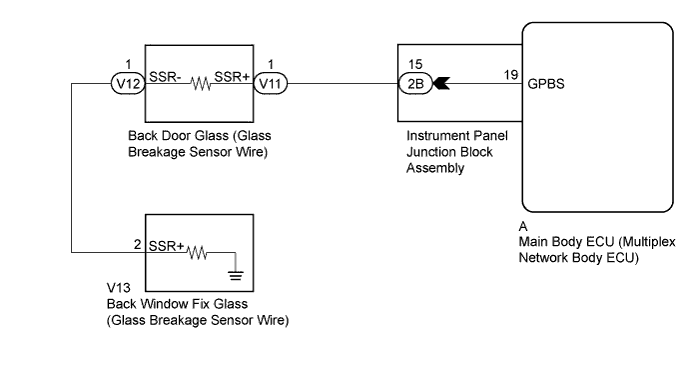
When the main body ECU (multiplex network body ECU) detects that back door glass (glass breakage sensor wire) is broken, the theft deterrent system switches from the armed state to the alarm sounding state.
WIRING DIAGRAM
INSPECTION PROCEDURE
PROCEDURE
-
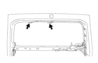
CHECK VEHICLE CONDITION (BACK DOOR GLASS AND BACK WINDOW FIX GLASS)
-
Check the vehicle condition (back door glass and back window fix glass).
Result Result Proceed to Back door glass is broken or back door glass and back window fix glass are broken. A Back window fix glass is broken. B
B 
INSPECT INSTRUMENT PANEL JUNCTION BLOCK ASSEMBLY Click here
A 
-
-
INSPECT INSTRUMENT PANEL JUNCTION BLOCK ASSEMBLY
-
Disconnect the A main body ECU (multiplex network body ECU) and 2B instrument panel junction block assembly connectors.
-
Measure the resistance according to the value(s) in the table below.
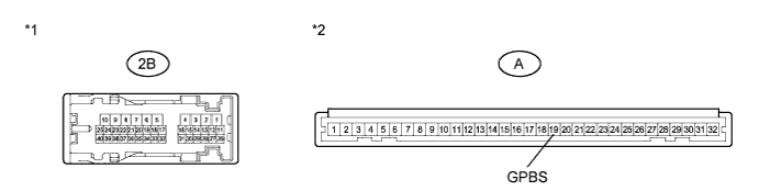
Standard Resistance Tester Connection Condition Specified Condition A-19 (GPBS) - 2B-15 Always Below 1 Ω Text in Illustration *1 Component without harness connected
(Instrument Panel Junction Block Assembly)
*2 Front view of wire harness connector
(to Main Body ECU (Multiplex Network Body ECU))
NG 
REPLACE INSTRUMENT PANEL JUNCTION BLOCK ASSEMBLY
OK
-
-
CHECK HARNESS AND CONNECTOR (INSTRUMENT PANEL JUNCTION BLOCK - BACK DOOR GLASS)
-
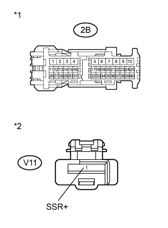
Text in Illustration *1 Front view of wire harness connector
(to Instrument Panel Junction Block Assembly)
*2 Front view of wire harness connector
(to Back Door Glass (Glass Breakage Sensor Wire))
Disconnect the V11 back door glass (glass breakage sensor wire) connector.
-
Measure the resistance according to the value(s) in the table below.
Standard Resistance Tester Connection Condition Specified Condition 2B-15 - V11-1 (SSR+) Always Below 1 Ω V11-1 (SSR+) - Body ground Always 10 kΩ or higher
NG
REPAIR OR REPLACE HARNESS OR CONNECTOR
OK 
REPLACE MAIN BODY ECU (MULTIPLEX NETWORK BODY ECU) Click here
-
-
INSPECT INSTRUMENT PANEL JUNCTION BLOCK ASSEMBLY
-
Disconnect the A main body ECU (multiplex network body ECU) and 2B instrument panel junction block assembly connectors.
-
Measure the resistance according to the value(s) in the table below.
Standard Resistance Tester Connection Condition Specified Condition A-19 (GPBS) - 2B-15 Always Below 1 Ω Text in Illustration *1 Component without harness connected
(Instrument Panel Junction Block Assembly)
*2 Front view of wire harness connector
(to Main Body ECU (Multiplex Network Body ECU))
NG
REPLACE INSTRUMENT PANEL JUNCTION BLOCK ASSEMBLY
OK
-
-
CHECK HARNESS AND CONNECTOR (INSTRUMENT PANEL JUNCTION BLOCK - BACK DOOR GLASS)
-
Text in Illustration *1 Front view of wire harness connector
(to Instrument Panel Junction Block Assembly)
*2 Front view of wire harness connector
(to Back Door Glass (Glass Breakage Sensor Wire))
Disconnect the V11 back door glass (glass breakage sensor wire) connector.
-
Measure the resistance according to the value(s) in the table below.
Standard Resistance Tester Connection Condition Specified Condition 2B-15 - V11-1 (SSR+) Always Below 1 Ω V11-1 (SSR+) - Body ground Always 10 kΩ or higher
NG
REPAIR OR REPLACE HARNESS OR CONNECTOR
OK
-
-
INSPECT BACK DOOR GLASS (GLASS BREAKAGE SENSOR WIRE)
-
Disconnect the V12 back door glass (glass breakage sensor wire) connector.
-
Measure the resistance according to the value(s) in the table below.
Standard Resistance Tester Connection Condition Specified Condition 1 (SSR+) - 1 (SSR-) Always Below 1 Ω 1 (SSR+) - 1 (SSR-) Always 10 kΩ or higher
NG
REPLACE BACK DOOR GLASS (GLASS BREAKAGE SENSOR WIRE) Click here
OK
-
-
CHECK HARNESS AND CONNECTOR (BACK DOOR GLASS - BACK WINDOW FIX GLASS)
-
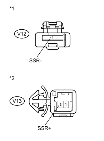
Text in Illustration *1 Front view of wire harness connector
(to Back Door Glass (Glass Breakage Sensor Wire))
*2 Front view of wire harness connector
(to Back Window Fix Glass (Glass Breakage Sensor Wire))
Disconnect the V13 back window fix glass (glass breakage sensor wire) connector.
-
Measure the resistance according to the value(s) in the table below.
Standard Resistance Tester Connection Condition Specified Condition V12-1 (SSR-) - V13-2 (SSR+) Always Below 1 Ω V12-1 (SSR-) - V13-2 (SSR+) Always 10 kΩ or higher
NG
REPAIR OR REPLACE HARNESS OR CONNECTOR
OK
REPLACE MAIN BODY ECU (MULTIPLEX NETWORK BODY ECU) Click here
-