ENGINE IMMOBILISER SYSTEM Security Indicator Light Does not Blinking
DESCRIPTION
The security indicator light blinks continuously due to a continuous signal received from the certification ECU (smart key ECU assembly) while the engine immobiliser is set.
WIRING DIAGRAM
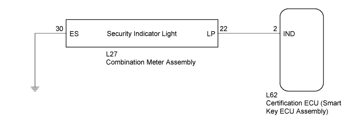
INSPECTION PROCEDURE
Note
-
If the certification ECU (smart key ECU assembly) is replaced, register all the keys and ECU communication ID.*1
-
If the certification ECU (smart key ECU assembly) is replaced, register all the keys.*2
-
*1: w/o Airbag Cut-off Switch
-
*2: w/ Airbag Cut-off Switch
PROCEDURE
-
PERFORM ACTIVE TEST USING INTELLIGENT TESTER
-
Connect the intelligent tester to the DLC3.
-
Turn the power switch on (IG).
-
Turn the intelligent tester on.
-
Enter the following menus: Body / Entry & Start / Active Test.
-
Perform the Active Test according to the display on the intelligent tester.
Entry & Start (Certification ECU (Smart Key ECU Assembly)) Tester Display Test Part Control Range Diagnostic Note Immobiliser Indicator Security indicator light ON or OFF - OK The security indicator light turns on and off according to operation via the intelligent tester.
NG 
INSPECT COMBINATION METER ASSEMBLY Click here
OK 
REPLACE CERTIFICATION ECU (SMART KEY ECU ASSEMBLY)
-
-
INSPECT COMBINATION METER ASSEMBLY
-
Disconnect the combination meter assembly.
-
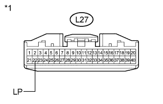
Text in Illustration *1 Front view of wire harness connector
(to Combination Meter Assembly)
Measure the voltage according to the value(s) in the table below.
Standard Voltage Tester Connection Condition Specified Condition L27-22 (LP) - Body ground
-
Power switch on (IG)
-
Security indicator light off
Below 2 V L27-22 (LP) - Body ground
-
Power switch off
-
Security indicator light blinks
Pulse generation -
NG
CHECK HARNESS AND CONNECTOR (CERTIFICATION ECU - COMBINATION METER ASSEMBLY) Click here
OK 
-
-
CHECK HARNESS AND CONNECTOR (COMBINATION METER ASSEMBLY - BODY GROUND)
-
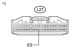
Text in Illustration *1 Front view of wire harness connector
(to Combination Meter Assembly)
Measure the resistance according to the value(s) in the table below.
Standard Resistance Tester Connection Condition Specified Condition L27-30 (ES) - Body ground Always Below 1 Ω
NG 
REPAIR OR REPLACE HARNESS OR CONNECTOR
OK
REPLACE NO. 3 METER CIRCUIT PLATE Click here
-
-
CHECK HARNESS AND CONNECTOR (CERTIFICATION ECU - COMBINATION METER ASSEMBLY)
-
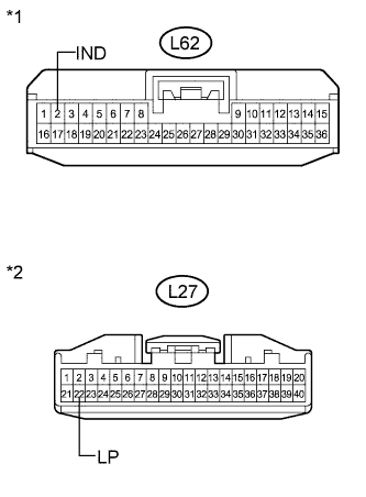
Text in Illustration *1 Front view of wire harness connector
(to Certification ECU (Smart Key ECU Assembly))
*2 Front view of wire harness connector
(to Combination Meter Assembly)
Disconnect the certification ECU (smart key ECU assembly) connector.
-
Measure the resistance according to the value(s) in the table below.
Standard Resistance Tester Connection Condition Specified Condition L62-2 (IND) - L27-22 (LP) Always Below 1 Ω L62-2 (IND) - Body ground Always 10 kΩ or higher L27-22 (LP) - Body ground Always 10 kΩ or higher
NG
REPAIR OR REPLACE HARNESS OR CONNECTOR
OK
REPLACE CERTIFICATION ECU (SMART KEY ECU ASSEMBLY)
-