ENGINE IMMOBILISER SYSTEM, Diagnostic DTC:B279A

| DTC Code | DTC Name |
|---|---|
| B279A | Theft Deterrent System Communication Line High Fixation |
DESCRIPTION
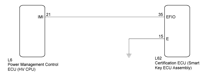
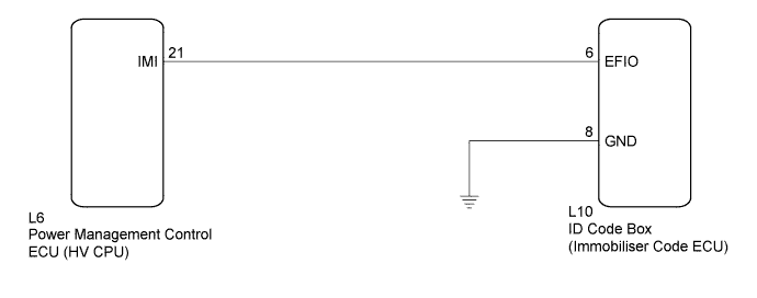
If the communication line (EFIO - IMI) to the certification ECU assembly (smart key ECU assembly)*1 or ID code box (immobiliser code ECU)*2 is stuck high output (e. g. shorted to +B), the power management control ECU (HV CPU) stores this DTC.
-
*1: w/o Airbag Cut-off Switch
-
*2: w/ Airbag Cut-off Switch
| DTC No. | DTC Detection Condition | Trouble Area |
|---|---|---|
| B279A | When the communication line (EFIO - IMI) between power management control ECU (HV CPU) and certification ECU assembly (smart key ECU assembly)*1 or ID code box (immobiliser code ECU)*2 is stuck high output. |
|
-
*1: w/o Airbag Cut-off Switch
-
*2: w/ Airbag Cut-off Switch
WIRING DIAGRAM
-
w/o Airbag Cut-off Switch
-
w/ Airbag Cut-off Switch
INSPECTION PROCEDURE
Note
-
If the certification ECU (smart key ECU assembly) is replaced, register all the keys and ECU communication ID.*1
-
If the ID code box (immobiliser code ECU) is replaced, register the ECU code and ECU communication ID.*2
-
*1: w/o Airbag Cut-off Switch
-
*2: w/ Airbag Cut-off Switch
PROCEDURE
-
CHECK DTC OUTPUT
-
Clear the DTCs Click here.
-
Recheck for DTCs Click here.
Tech Tips
If any DTCs other than DTC B279A are output, troubleshoot those DTCs first.
Result Result Proceed to DTC B279A is output A DTC B279A and other DTCs are output B
B 
GO TO DIAGNOSTIC TROUBLE CODE CHART Click here
A 
-
-
SYSTEM CHECK
-
Check the vehicle specification.
Result Result Proceed to w/o Airbag Cut-off Switch A w/ Airbag Cut-off Switch B
B 
CHECK HARNESS AND CONNECTOR (ID CODE BOX - POWER MANAGEMENT CONTROL ECU (HV CPU)) Click here
A
-
-
CHECK HARNESS AND CONNECTOR (CERTIFICATION ECU - POWER MANAGEMENT CONTROL ECU (HV CPU))
-
Disconnect the certification ECU (smart key ECU assembly) connector.
-
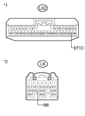
Text in Illustration *1 Front view of wire harness connector
(to Certification ECU (Smart Key ECU Assembly))
*2 Front view of wire harness connector
(to Power Management Control ECU (HV CPU))
Disconnect the power management control ECU (HV CPU) connector.
-
Measure the resistance and voltage according to the value(s) in the table below.
Standard Resistance Tester Connection Condition Specified Condition L62-35 (EFIO) - L6-21 (IMI) Always Below 1 Ω L6-21 (IMI) - Body ground Always 10 kΩ or higher Standard Voltage Tester Connection Condition Specified Condition L6-21 (IMI) - Body ground Always Below 1 V
NG
REPAIR OR REPLACE HARNESS OR CONNECTOR
OK
-
-
CHECK CERTIFICATION ECU (SMART KEY ECU ASSEMBLY) (WAVEFORM)
-
Reconnect the certification ECU (smart key ECU assembly) connector.
-
Reconnect the power management control ECU (HV CPU) connector.
-
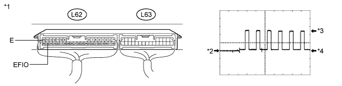
Using an oscilloscope, check the waveform.
Waveform (Reference) Item Content Terminal No. (Symbol) L62-35 (EFIO) - L62-15 (E) Tool Setting 5 V/DIV., 50 msec./DIV. Condition Power switch on (IG) OK Waveform is output normally (see illustration). Text in Illustration *1 Component with harness connected
(Certification ECU (Smart Key ECU Assembly))
*2 GND *3 HIGH *4 LOW
NG
REPLACE CERTIFICATION ECU (SMART KEY ECU ASSEMBLY) Click here
OK 
REPLACE POWER MANAGEMENT CONTROL ECU (HV CPU) Click here
-
-
REPLACE CERTIFICATION ECU (SMART KEY ECU ASSEMBLY)
-
Replace the certification ECU (smart key ECU assembly).
NEXT
-
-
KEY REGISTRATION
-
Register the key.
NEXT
-
-
ECU COMMUNICATION ID REGISTRATION
-
Register the ECU communication ID.
NEXT
-
-
CHECK DTC OUTPUT
-
Clear the DTCs Click here.
-
Recheck for DTCs Click here.
OK DTC B279A is not output.
NG
REPLACE POWER MANAGEMENT CONTROL ECU (HV CPU) Click here
OK
END (CERTIFICATION ECU (SMART KEY ECU ASSEMBLY) WAS DEFECTIVE)
-
-
CHECK HARNESS AND CONNECTOR (ID CODE BOX - POWER MANAGEMENT CONTROL ECU (HV CPU))
-
Disconnect the ID code box (immobiliser code ECU) connector.
-
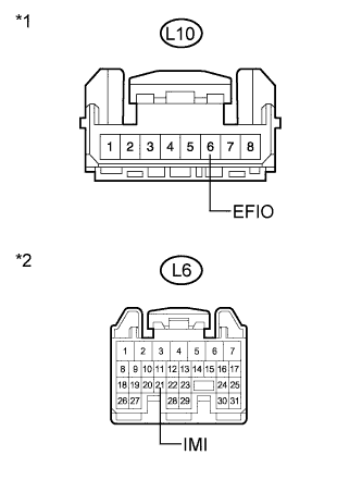
Text in Illustration *1 Front view of wire harness connector
(to ID Code Box (Immobiliser Code ECU))
*2 Front view of wire harness connector
(to Power Management Control ECU (HV CPU))
Disconnect the power management control ECU (HV CPU) connector.
-
Measure the resistance and voltage according to the value(s) in the table below.
Standard Resistance Tester Connection Condition Specified Condition L10-6 (EFIO) - L6-21 (IMI) Always Below 1 Ω L6-21 (IMI) - Body ground Always 10 kΩ or higher Standard Voltage Tester Connection Condition Specified Condition L6-21 (IMI) - Body ground Always Below 1 V
NG
REPAIR OR REPLACE HARNESS OR CONNECTOR
OK
-
-
CHECK ID CODE BOX (IMMOBILISER CODE ECU) (WAVEFORM)
-
Reconnect the ID code box (immobiliser code ECU) connector.
-
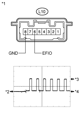
Text in Illustration *1 Component with harness connected
(ID Code Box (Immobiliser Code ECU))
*2 GND *3 HIGH *4 LOW Reconnect the power management control ECU (HV CPU) connector.
-
Using an oscilloscope, check the waveform.
Waveform (Reference) Item Content Terminal No. (Symbol) L10-6 (EFIO) - L10-8 (GND) Tool Setting 5 V/DIV., 50 msec./DIV. Condition Power switch on (IG) OK Waveform is output normally (see illustration).
NG
REPLACE ID CODE BOX (IMMOBILISER CODE ECU) Click here
OK
REPLACE POWER MANAGEMENT CONTROL ECU (HV CPU) Click here
-
-
REPLACE ID CODE BOX (IMMOBILISER CODE ECU)
-
Replace the ID code box (immobiliser code ECU).
NEXT
-
-
ECU CODE REGISTRATION
-
Register the ECU code.
NEXT
-
-
ECU COMMUNICATION ID REGISTRATION
-
Register the ECU communication ID.
NEXT
-
-
CHECK DTC OUTPUT
-
Clear the DTCs Click here.
-
Recheck for DTCs Click here.
OK DTC B279A is not output.
NG
REPLACE POWER MANAGEMENT CONTROL ECU (HV CPU) Click here
OK
END (ID CODE BOX (IMMOBILISER CODE ECU) WAS DEFECTIVE)
-