ENGINE IMMOBILISER SYSTEM, Diagnostic DTC:B2799

| DTC Code | DTC Name |
|---|---|
| B2799 | Engine Immobiliser System Malfunction |
DESCRIPTION
This DTC is stored when one of the following occurs: 1) the power management control ECU (HV CPU) detects an error in its own communication with the certification ECU assembly (smart key ECU assembly)*1 or ID code box (immobiliser code ECU)*2; 2) the power management control ECU (HV CPU) detects an error in the communication lines; or 3) the ECU communication ID between the certification ECU assembly (smart key ECU assembly)*1 or ID code box (immobiliser code ECU)*2 and power management control ECU (HV CPU) is different and a hybrid vehicle control system start is attempted.
-
*1: w/o Airbag Cut-off Switch
-
*2: w/ Airbag Cut-off Switch
Tech Tips
Before troubleshooting this DTC, make sure that no certification ECU (smart key ECU assembly) DTCs are present. If present, troubleshoot the certification ECU (smart key ECU assembly) DTCs first.
| DTC No. | DTC Detection Condition | Trouble Area |
|---|---|---|
| B2799 | One of the following conditions is met:
|
|
-
*1: w/o Airbag Cut-off Switch
-
*2: w/ Airbag Cut-off Switch
-
*3: w/ Blocking System
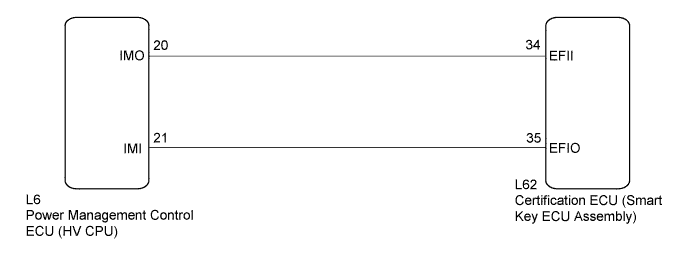
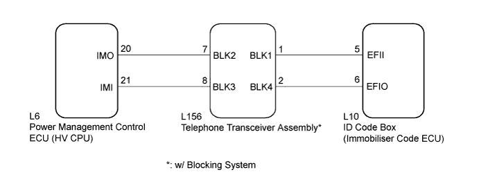
WIRING DIAGRAM
-
w/o Airbag Cut-off Switch
-
w/ Airbag Cut-off Switch
INSPECTION PROCEDURE
Note
-
If the certification ECU (smart key ECU assembly) is replaced, register all the keys and ECU communication ID.*1
-
If the ID code box (immobiliser code ECU) is replaced, register the ECU code and ECU communication ID.*2
-
When the telephone transceiver assembly is replaced, it is necessary to set the contract mode.*3
-
*1: w/o Airbag Cut-off Switch
-
*2: w/ Airbag Cut-off Switch
-
*3: w/ Blocking System
PROCEDURE
-
CHECK DTC OUTPUT
-
Clear the DTCs Click here.
-
Recheck for DTCs Click here.
OK DTC B2799 is not output.
NG 
RE-REGISTER ECU COMMUNICATION ID Click here
OK 
USE SIMULATION METHOD TO CHECK Click here
-
-
RE-REGISTER ECU COMMUNICATION ID
-
Re-register the ECU communication ID.
NEXT 
-
-
CHECK DTC OUTPUT
-
Clear the DTCs Click here.
-
Recheck for DTCs Click here.
OK DTC B2799 is not output.
NG
CHECK CONNECTOR CONNECTION CONDITION Click here
OK
END (ECU COMMUNICATION ID WAS NOT REGISTERED CORRECTLY)
-
-
CHECK CONNECTOR CONNECTION CONDITION
-
Turn the power switch off.
-
Check that the connectors are properly connected to the power management control ECU (HV CPU) and certification ECU (smart key ECU assembly)*1 or ID code box (immobiliser code ECU)*2.
-
*1: w/o Airbag Cut-off Switch
-
*2: w/ Airbag Cut-off Switch
OK Connectors are properly connected. -
NG 
CONNECT CONNECTORS PROPERLY
OK
-
-
SYSTEM CHECK
-
Check the vehicle specification.
Result Result Proceed to w/o Airbag Cut-off Switch A w/ Airbag Cut-off Switch B
B
CHECK HARNESS AND CONNECTOR (ID CODE BOX - POWER MANAGEMENT CONTROL ECU (HV CPU)) Click here
A
-
-
CHECK HARNESS AND CONNECTOR (CERTIFICATION ECU - POWER MANAGEMENT CONTROL ECU (HV CPU))
-
Disconnect the certification ECU (smart key ECU assembly) connector.
-
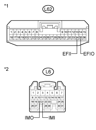
Text in Illustration *1 Front view of wire harness connector
(to Certification ECU (Smart Key ECU Assembly))
*2 Front view of wire harness connector
(to Power Management Control ECU (HV CPU))
Disconnect the power management control ECU (HV CPU) connector.
-
Measure the resistance and voltage according to the value(s) in the table below.
Standard Resistance Tester Connection Condition Specified Condition L62-34 (EFII) - L6-20 (IMO) Always Below 1 Ω L62-35 (EFIO) - L6-21 (IMI) Always Below 1 Ω L6-20 (IMO) - Body ground Always 10 kΩ or higher L6-21 (IMI) - Body ground Always 10 kΩ or higher Standard Voltage Tester Connection Condition Specified Condition L6-20 (IMO) - Body ground Always Below 1 V L6-21 (IMI) - Body ground Always Below 1 V
NG
REPAIR OR REPLACE HARNESS OR CONNECTOR
OK
-
-
REPLACE POWER MANAGEMENT CONTROL ECU (HV CPU)
-
Replace the power management control ECU (HV CPU) Click here.
NEXT
-
-
CHECK DTC OUTPUT
-
Clear the DTCs Click here.
-
Recheck for DTCs Click here.
OK DTC B2799 is not output.
NG
REPLACE CERTIFICATION ECU (SMART KEY ECU ASSEMBLY)
OK
END (POWER MANAGEMENT CONTROL ECU (HV CPU) WAS DEFECTIVE)
-
-
SYSTEM CHECK
-
Check the vehicle specification.
Result Result Proceed to w/o Blocking System A w/ Blocking System B
B
CHECK HARNESS AND CONNECTOR (POWER MANAGEMENT CONTROL ECU - TELEPHONE TRANSCEIVER ASSEMBLY) Click here
A
-
-
CHECK HARNESS AND CONNECTOR (ID CODE BOX - POWER MANAGEMENT CONTROL ECU (HV CPU))
-
Disconnect the ID code box (immobiliser code ECU) connector.
-
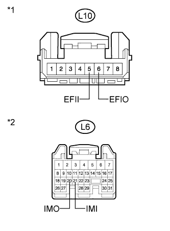
Text in Illustration *1 Front view of wire harness connector
(to ID Code Box (Immobiliser Code ECU))
*2 Front view of wire harness connector
(to Power Management Control ECU (HV CPU))
Disconnect the power management control ECU (HV CPU) connector.
-
Measure the resistance and voltage according to the value(s) in the table below.
Standard Resistance Tester Connection Condition Specified Condition L10-5 (EFII) - L6-20 (IMO) Always Below 1 Ω L10-6 (EFIO) - L6-21 (IMI) Always Below 1 Ω L6-20 (IMO) - Body ground Always 10 kΩ or higher L6-21 (IMI) - Body ground Always 10 kΩ or higher Standard Voltage Tester Connection Condition Specified Condition L6-20 (IMO) - Body ground Always Below 1 V L6-21 (IMI) - Body ground Always Below 1 V
NG
REPAIR OR REPLACE HARNESS OR CONNECTOR
OK
-
-
REPLACE POWER MANAGEMENT CONTROL ECU (HV CPU)
-
Replace the power management control ECU (HV CPU) Click here.
NEXT
-
-
CHECK DTC OUTPUT
-
Clear the DTCs Click here.
-
Recheck for DTCs Click here.
OK DTC B2799 is not output.
NG
REPLACE ID CODE BOX (IMMOBILISER CODE ECU)
OK
END (POWER MANAGEMENT CONTROL ECU (HV CPU) WAS DEFECTIVE)
-
-
CHECK HARNESS AND CONNECTOR (POWER MANAGEMENT CONTROL ECU - TELEPHONE TRANSCEIVER ASSEMBLY)
-
Disconnect the power management control ECU connector.
-
Disconnect the telephone transceiver assembly connector.
-
Measure the resistance according to the value(s) in the table below.
Standard Resistance Tester Connection Condition Specified Condition L156-8 (BLK3) - L6-21 (IMI) Always Below 1 Ω L6-20 (IMO) - Body ground Always 10 kΩ or higher L156-7 (BLK2) - L6-20 (IMO) Always Below 1 Ω L6-21 (IMI) - Body ground Always 10 kΩ or higher
NG
REPAIR OR REPLACE HARNESS OR CONNECTOR
OK
-
-
CHECK HARNESS AND CONNECTOR (ID CODE BOX (IMMOBILISER CODE ECU) - TELEPHONE TRANSCEIVER ASSEMBLY)
-
Disconnect the ID code box (immobiliser code ECU) connector.
-
Measure the resistance according to the value(s) in the table below.
Standard Resistance Tester Connection Condition Specified Condition L156-1 (BLK1) - L10-5 (EFII) Always Below 1 Ω L10-6 (EFIO) - Body ground Always 10 kΩ or higher L156-2 (BLK4) - L10-6 (EFIO) Always Below 1 Ω L10-5 (EFII) - Body ground Always 10 kΩ or higher
NG
REPAIR OR REPLACE HARNESS OR CONNECTOR
OK
-
-
ECU COMMUNICATION ID REGISTRATION
-
Register the ECU communication ID.
Tech Tips
Refer to the Service Bulletin.
NEXT
-
-
CLEAR DTC
-
Clear the DTCs Click here.
NEXT
-
-
CHECK DTC OUTPUT
-
Check for DTCs Click here.
Tech Tips
Before checking for DTCs, perform the "DTC Output Confirmation Operation" procedure.
OK DTC B2799 is not output.
NG
REPLACE TELEPHONE TRANSCEIVER ASSEMBLY Click here
OK
END (ECU COMMUNICATION ID HAS NOT BEEN REGISTERED)
-
-
REPLACE TELEPHONE TRANSCEIVER ASSEMBLY
-
Temporarily replace the telephone transceiver assembly with a new or known good one.
Tech Tips
Refer to the Service Bulletin.
NEXT
-
-
ECU COMMUNICATION ID REGISTRATION
-
Register the ECU communication ID.
Tech Tips
Refer to the Service Bulletin.
NEXT
-
-
CLEAR DTC
-
Clear the DTCs Click here.
NEXT
-
-
CHECK DTC OUTPUT
-
Check for DTCs Click here.
Tech Tips
Before checking for DTCs, perform the "DTC Output Confirmation Operation" procedure.
OK DTC B2799 is not output.
NG
REPLACE POWER MANAGEMENT CONTROL ECU (HV CPU) Click here
OK
END (TELEPHONE TRANSCEIVER ASSEMBLY WAS DEFECTIVE)
-
-
REPLACE POWER MANAGEMENT CONTROL ECU (HV CPU)
-
Replace the power management control ECU (HV CPU) Click here.
NEXT
-
-
CHECK DTC OUTPUT
-
Clear the DTCs Click here.
-
Recheck for DTCs Click here.
OK DTC B2799 is not output.
NG
REPLACE ID CODE BOX (IMMOBILISER CODE ECU)
OK
END (POWER MANAGEMENT CONTROL ECU (HV CPU) WAS DEFECTIVE)
-