THEFT DETERRENT SYSTEM Intrusion Sensor Cancel Switch Circuit
DESCRIPTION
-
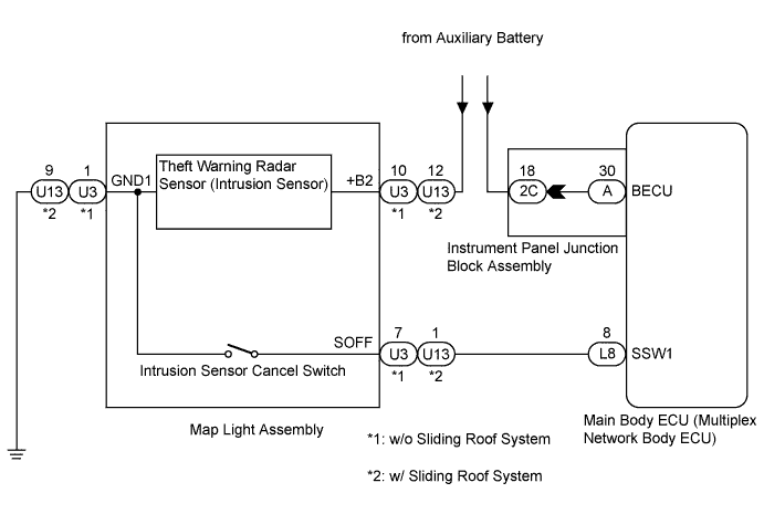
When the intrusion sensor cancel switch on the map light assembly is pressed, the sensor off signal is sent to the main body ECU (multiplex network body ECU) which causes the intrusion sensor to stop operating.
WIRING DIAGRAM
INSPECTION PROCEDURE
PROCEDURE
-
READ VALUE USING INTELLIGENT TESTER (INTRUSION SENSOR CANCEL SWITCH)
-
Connect the intelligent tester to the DLC3.
-
Turn the power switch on (IG).
-
Turn the intelligent tester on.
-
Select the item below in the Data List and read the display on the intelligent tester.
Main Body Tester Display Measurement Item/Range Normal Condition Diagnostic Note Intrusion Sens OFF SW Intrusion sensor cancel switch/ON or OFF ON: Intrusion sensor cancel switch on
OFF: Intrusion sensor cancel switch off
- OK The indicator on the intelligent tester switches between ON and OFF in accordance with the intrusion sensor cancel switch status.
NG 
CHECK HARNESS AND CONNECTOR (MAIN BODY ECU - MAP LIGHT ASSEMBLY) Click here
OK 
REPLACE MAIN BODY ECU (MULTIPLEX NETWORK BODY ECU) Click here
-
-
CHECK HARNESS AND CONNECTOR (MAIN BODY ECU - MAP LIGHT ASSEMBLY)
-
Disconnect the L8 main body ECU (multiplex network body ECU) and U3*4 or U13*5 map light assembly connectors.
-
Measure the resistance according to the value(s) in the table below.
Standard Resistance Tester Connection Condition Specified Condition L8-8 (SSW1) - U3-7 (SOFF)*4
L8-8 (SSW1) - U13-1 (SOFF)*5
Always Below 1 Ω U3-1 (GND1) - Body ground*4
U13-9 (GND1) - Body ground*5
Always Below 1 Ω L8-8 (SSW1) - Body ground Always 10 kΩ or higher
-
*4: w/o Sliding Roof System
-
*5: w/ Sliding Roof System
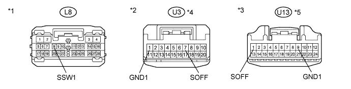
Text in Illustration *1 Front view of wire harness connector
(to Main Body ECU (Multiplex Network Body ECU))
*2 Front view of wire harness connector
(to Map Light Assembly (Intrusion Sensor))
*3 Front view of wire harness connector
(to Map Light Assembly (Intrusion Sensor))
*4 w/o Sliding Roof System *5 w/ Sliding Roof System - - -
NG 
REPAIR OR REPLACE HARNESS OR CONNECTOR
OK 
-
-
INSPECT MAP LIGHT ASSEMBLY (INTRUSION SENSOR CANCEL SWITCH)
-
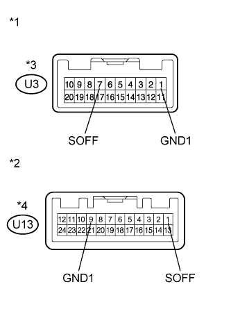
Text in Illustration *1 Component without harness connected
(Map Light Assembly (Intrusion Sensor Cancel Switch))
*2 Component without harness connected
(Map Light Assembly (Intrusion Sensor Cancel Switch))
*3 w/o Sliding Roof System *4 w/ Sliding Roof System Remove the map light assembly (intrusion sensor cancel switch) Click here.
-
Measure the resistance according to the value(s) in the table below.
Standard Resistance Tester Connection Condition Specified Condition U3-7 (SOFF) - U3-1 (GND1)*3
U13-1 (SOFF) - U13-9 (GND1)*4
Intrusion sensor ON (intrusion sensor cancel switch not pressed) 10 kΩ or higher U3-7 (SOFF) - U3-1 (GND1)*3
U13-1 (SOFF) - U13-9 (GND1)*4
Intrusion sensor off (intrusion sensor cancel switch pressed) Below 1 Ω
-
*3: w/o Sliding Roof System
-
*4: w/ Sliding Roof System
-
NG
REPLACE MAP LIGHT ASSEMBLY (INTRUSION SENSOR CANCEL SWITCH) Click here
OK
REPLACE MAIN BODY ECU (MULTIPLEX NETWORK BODY ECU) Click here
-