THEFT DETERRENT SYSTEM Security Horn Circuit
DESCRIPTION
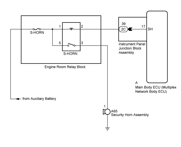
When the theft deterrent system is switched from the armed state to the alarm sounding state, the main body ECU (multiplex network body ECU) controls the security horn.
WIRING DIAGRAM
INSPECTION PROCEDURE
Note
Inspect the fuses for circuits related to this system before performing the following inspection procedure.
PROCEDURE
-
PERFORM ACTIVE TEST USING INTELLIGENT TESTER
-
Connect the intelligent tester to the DLC3.
-
Turn the power switch on (IG).
-
Turn the intelligent tester on.
-
Select the item below in the Active Test and then check that the security horn assembly operates.
Body Tester Display Test Part Control Range Diagnostic Note Security Horn Security horn ON/OFF - OK The security horn assembly sounds and stops correctly when operated through the intelligent tester.
NG 
INSPECT SECURITY HORN ASSEMBLY Click here
OK 
REPLACE MAIN BODY ECU (MULTIPLEX NETWORK BODY ECU) Click here
-
-
INSPECT SECURITY HORN ASSEMBLY
-
Remove the security horn assembly Click here.
-
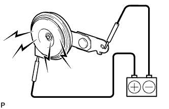
Check the operation of the security horn assembly.
OK Battery Connection Specified Condition Battery positive (+) → A65-1 Horn sounds Battery negative (-) → Horn body
NG 
REPLACE SECURITY HORN ASSEMBLY Click here
OK 
-
-
INSPECT INSTRUMENT PANEL JUNCTION BLOCK ASSEMBLY
-
Disconnect the 2C instrument panel junction block assembly and A main body ECU (multiplex network body ECU) connectors.
-
Measure the resistance according to the value(s) in the table below.
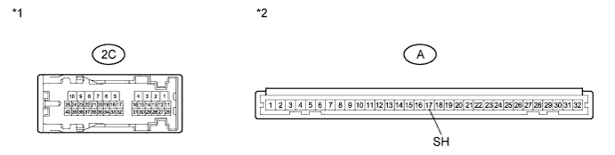
Standard Resistance Tester Connection Condition Specified Condition 2C-39 - A-17 (SH) Always Below 1 Ω Text in Illustration *1 Component without harness connected
(Instrument Panel Junction Block Assembly)
*2 Front view of wire harness connector
(to Main Body ECU (Multiplex Network Body ECU))
NG
REPLACE INSTRUMENT PANEL JUNCTION BLOCK ASSEMBLY
OK
-
-
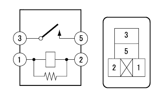
INSPECT S-HORN RELAY
-
Remove the S-HORN relay from the engine room relay block.
-
Measure the resistance according to the value(s) in the table below.
Standard Resistance Tester Connection Condition Specified Condition 3 - 5 Battery voltage supplied between terminals 1 and 2 Below 1 Ω 3 - 5 Battery voltage not supplied between terminals 1 and 2 10 kΩ or higher
NG
REPLACE S-HORN RELAY
OK
-
-
CHECK HARNESS AND CONNECTOR (S-HORN RELAY POWER SOURCE)
-
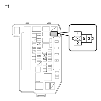
Text in Illustration *1 Front view of wire harness connector
(to Engine Room Relay Block (S-HORN Relay))
Measure the voltage according to the value(s) in the table below.
Standard Voltage Tester Connection Condition Specified Condition 1 - Body ground Always 11 to 14 V 5 - Body ground Always 11 to 14 V
NG
REPAIR OR REPLACE HARNESS OR CONNECTOR
OK
-
-
CHECK HARNESS AND CONNECTOR (S-HORN RELAY - INSTRUMENT PANEL JUNCTION BLOCK)
-
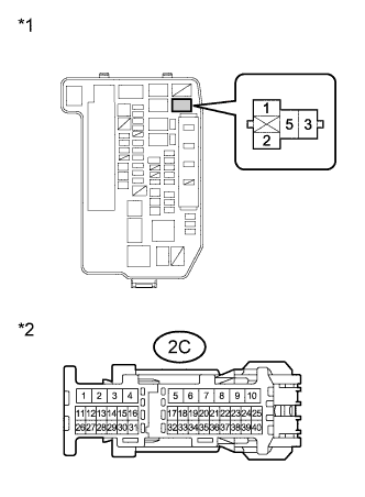
Text in Illustration *1 Front view of wire harness connector
(to Engine Room Relay Block (S-HORN Relay))
*2 Front view of wire harness connector
(to Instrument Panel Junction Block Assembly)
Measure the resistance according to the value(s) in the table below.
Standard Resistance Tester Connection Condition Specified Condition 2 - 2C-39 Always Below 1 Ω 2C-39 - Body ground Always 10 kΩ or higher
NG
REPAIR OR REPLACE HARNESS OR CONNECTOR
OK
-
-
CHECK HARNESS AND CONNECTOR (SECURITY HORN ASSEMBLY - S-HORN RELAY)
-
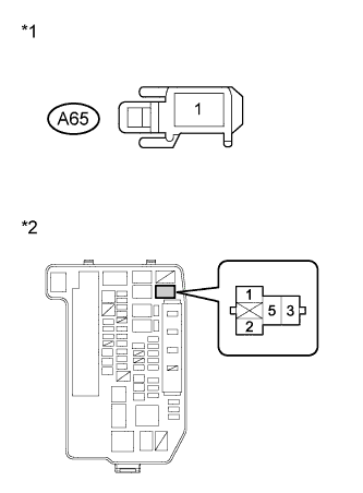
Text in Illustration *1 Front view of wire harness connector
(to Security Horn Assembly)
*2 Front view of wire harness connector
(to Engine Room Relay Block (S-HORN Relay))
Disconnect the A65 security horn assembly connector.
-
Measure the resistance according to the value(s) in the table below.
Standard Resistance Tester Connection Condition Specified Condition A65-1 - 3 Always Below 1 Ω A65-1 - Body ground Always 10 kΩ or higher
NG
REPAIR OR REPLACE HARNESS OR CONNECTOR
OK
REPLACE MAIN BODY ECU (MULTIPLEX NETWORK BODY ECU) Click here
-