POWER MANAGEMENT CONTROL ECU INSTALLATION

-
INSTALL POWER MANAGEMENT CONTROL ECU (for LHD)
-
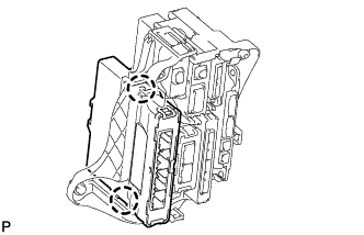
Engage the 2 claws to install the power management control ECU.
-
-
INSTALL ECU INTEGRATION BOX (for LHD)
-
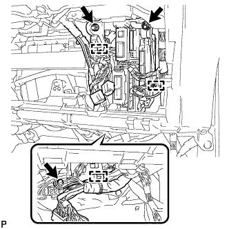
Install the ECU integration box with the 2 nuts and bolt.
- Torque:
- 14 N*m { 138 kgf*cm, 10 ft.*lbf }
-
Engage the 3 clamps to connect the wire harness.
-
Connect each connector.
-
-
INSTALL POWER MANAGEMENT CONTROL ECU (for RHD)
-
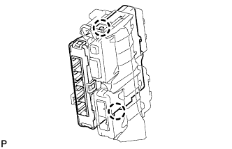
Engage the 2 claws to install the power management control ECU.
-
-
INSTALL ECU INTEGRATION BOX (for RHD)
-
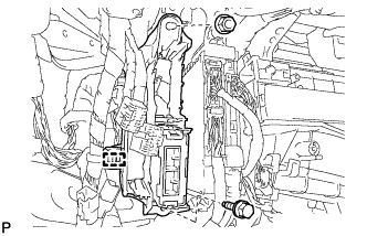
Install the ECU integration box with the nut and bolt.
- Torque:
- 14 N*m { 138 kgf*cm, 10 ft.*lbf }
-
Engage the clamp to connect the wire harness.
-
Connect each connector.
-
-
INSTALL GLOVE COMPARTMENT DOOR ASSEMBLY
-
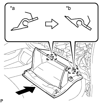
Text in Illustration *a Opened Approximately 55° *b Closed With the glove compartment door assembly opened approximately 55° from its closed position, engage the 2 hinges horizontally.
Note
Engaging the hinges from the top will deform the hinges. Be sure to install the glove compartment door assembly horizontally.
-
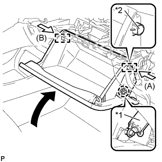
Text in Illustration *1 Glove Compartment Door Stopper Sub-assembly *2 Stopper Slightly bend the stoppers (A) and (B) in the directions indicated by the arrows in the illustration and engage the stoppers to install the glove compartment door assembly.
-
Engage the claw and connect the glove compartment door stopper sub-assembly.
-
-
INSTALL NO. 2 INSTRUMENT PANEL UNDER COVER SUB-ASSEMBLY
-
Connect the connector.
-
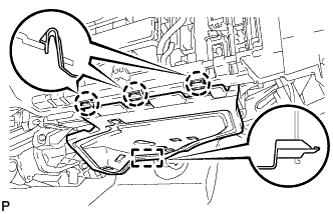
Engage the guide and 3 claws to install the No. 2 instrument panel under cover sub-assembly.
-
-
CONNECT CABLE TO NEGATIVE BATTERY TERMINAL
Note
When disconnecting the cable, some systems need to be initialized after the cable is reconnected Click here.