LIN COMMUNICATION SYSTEM, Diagnostic DTC:B2325

| DTC Code | DTC Name |
|---|---|
| B2325 | LIN Communication Bus Malfunction |
DESCRIPTION
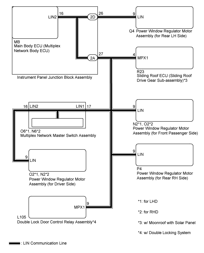
The main body ECU (multiplex network body ECU) monitors communication between all the ECUs connected to the door bus lines. When the main body ECU (multiplex network body ECU) detects errors in communication with all the ECUs connected to the door bus lines at 2.6-second intervals and 3 times in a row, DTC B2325 will be stored.
| DTC No. | DTC Detection Condition | Trouble Area |
|---|---|---|
| B2325 | Main body ECU (multiplex network body ECU) detects errors in communication with the ECUs connected to the door bus lines 3 times in a row. |
|
-
*1: w/ Moonroof with Solar Panel
-
*2: w/ Double Locking System
WIRING DIAGRAM
INSPECTION PROCEDURE
Note
-
When the sliding roof ECU (sliding roof drive gear assembly) is replaced or removed and reinstalled, it requires initialization Click here.
-
When a power window regulator motor assembly is replaced or removed and reinstalled, it requires initialization Click here.
-
When using the intelligent tester to troubleshoot with the power switch off:
Connect the intelligent tester to the DLC3, and turn the courtesy switch on and off at 1.5-second intervals until communication between the intelligent tester and vehicle begins.
PROCEDURE
-
CHECK HARNESS AND CONNECTOR (POWER WINDOW REGULATOR MOTOR (DRIVER SIDE) - MASTER SWITCH)
-
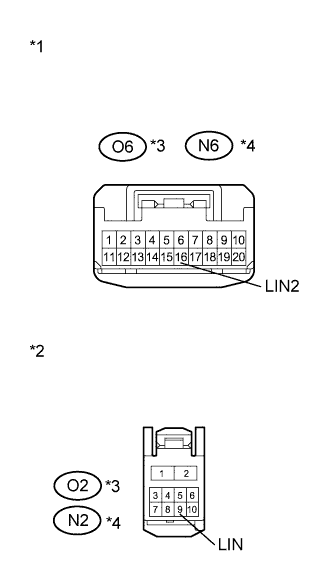
Text in Illustration *1 Front view of wire harness connector
(to Multiplex Network Master Switch Assembly)
*2 Front view of wire harness connector
(to Power Window Regulator Motor Assembly (for Driver Side))
*3 for LHD *4 for RHD Disconnect the O6*1 or N6*2 multiplex network master switch connector.
-
Disconnect the O2*1 or N2*2 power window regulator motor (for driver side) connector.
-
Measure the resistance according to the value(s) in the table below.
Standard Resistance Tester Connection Condition Specified Condition O6-16 (LIN2) - O2-9 (LIN)*1
N6-16 (LIN2) - N2-9 (LIN)*2
Always Below 1 Ω O6-16 (LIN2) - Body ground*1
N6-16 (LIN2) - Body ground*2
Always 10 kΩ or higher
-
*1: for LHD
-
*2: for RHD
-
NG 
REPAIR OR REPLACE HARNESS OR CONNECTOR
OK 
-
-
INSPECT MULTIPLEX NETWORK MASTER SWITCH ASSEMBLY
-
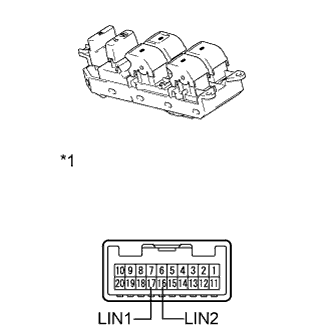
Text in Illustration *1 Component without harness connected
(Multiplex Network Master Switch Assembly)
Remove the multiplex network master switch assembly Click here.
-
Measure the resistance according to the value(s) in the table below.
Standard Resistance Tester Connection Condition Specified Condition 16 (LIN2) - 17 (LIN1) Always Below 1 Ω 16 (LIN2) - Body ground Always 10 kΩ or higher
NG
REPLACE MULTIPLEX NETWORK MASTER SWITCH ASSEMBLY Click here
OK
-
-
INSPECT INSTRUMENT PANEL JUNCTION BLOCK ASSEMBLY
-
Remove the instrument panel junction block assembly Click here.
-
Remove the main body ECU (multiplex network body ECU) from the instrument panel junction block assembly.
-
Measure the resistance according to the value(s) in the table below.
Tech Tips
This inspection is to check the LIN line in the instrument panel junction block assembly that connects the wire harness to the built-in main body ECU (multiplex network body ECU).
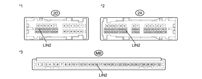
Standard Resistance Tester Connection Condition Specified Condition 2D-26 (LIN2) - MB-16 (LIN2) Always Below 1 Ω 2A-27 (LIN2) - MB-16 (LIN2) Always Below 1 Ω 2A-27 (LIN2) - Body ground Always 10 kΩ or higher Text in Illustration *1 Component without harness connected
(Instrument Panel Junction Block Assembly)
*2 Component without harness connected
(Instrument Panel Junction Block Assembly)
*3 Component without harness connected
(Instrument Panel Junction Block Assembly)
- -
NG
REPLACE INSTRUMENT PANEL JUNCTION BLOCK ASSEMBLY Click here
OK
-
-
CHECK HARNESS AND CONNECTOR (INSTRUMENT JUNCTION BLOCK - EACH ECU)
-
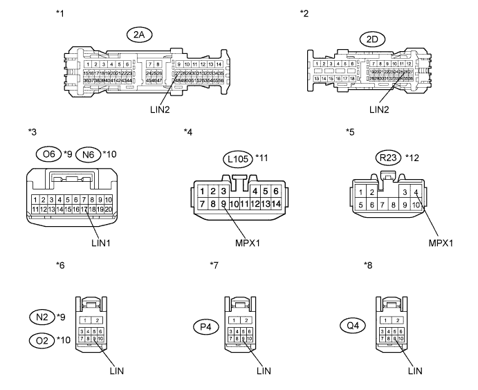
Disconnect the N2*1, O2*2, L105*3, R23*4, P4 and Q4 connectors.
-
Measure the resistance according to the value(s) in the table below.
Standard Resistance Tester Connection Condition Specified Condition 2D-26 (LIN2) - Q4-9 (LIN) Always Below 1 Ω 2A-27 (LIN2) - P4-9 (LIN) Always Below 1 Ω 2A-27 (LIN2) - O6-17 (LIN1)*1
2A-27 (LIN2) - N6-17 (LIN1)*2
Always Below 1 Ω 2A-27 (LIN2) - N2-9 (LIN)*1
2A-27 (LIN2) - O2-9 (LIN)*2
Always Below 1 Ω 2A-27 (LIN2) - L105-9 (MPX1)*3 Always Below 1 Ω 2A-27 (LIN2) - R23-4 (MPX1)*4 Always Below 1 Ω 2D-26 (LIN2) - Body ground Always 10 kΩ or higher 2A-27 (LIN2) - Body ground Always 10 kΩ or higher
-
*1: for LHD
-
*2: for RHD
-
*3: w/ Double Locking System
-
*4: w/ Moonroof with Solar Panel
Text in Illustration *1 Front view of wire harness connector
(to Instrument Panel Junction Block Assembly)
*2 Front view of wire harness connector
(to Instrument Panel Junction Block Assembly)
*3 Front view of wire harness connector
(to Multiplex Network Master Switch Assembly)
*4 Front view of wire harness connector
(to Double Lock Door Control Relay Assembly)
*5 Front view of wire harness connector
(to Sliding Roof ECU (Sliding Roof Driver Gear Sub-assembly))
*6 Front view of wire harness connector
(to Power Window Regulator Motor Assembly (for Front Passenger Side))
*7 Front view of wire harness connector
(to Power Window Regulator Motor Assembly (for Rear RH Side))
*8 Front view of wire harness connector
(to Power Window Regulator Motor Assembly (for Rear LH Side))
*9 for LHD *10 for RHD *11 w/ Double Locking System *12 w/ Moonroof with Solar Panel -
NG
REPAIR OR REPLACE HARNESS OR CONNECTOR
OK
-
-
CHECK DTC OUTPUT (POWER WINDOW REGULATOR MOTOR ASSEMBLY (for REAR LH SIDE))
-
Reconnect the O6*1, N6*2, L105*3, 2A, 2D, R23*4, P4, O2 and N2 connectors.
-
*1: for LHD
-
*2: for RHD
-
*3: w/ Double Locking System
-
*4: w/ Moonroof with Solar Panel
-
-
Clear the DTC Click here.
-
After 10 seconds have elapsed, check if the trouble occurs again.
-
Check for DTCs again.
Result Result Proceed to DTC B2325 is output A DTC B2325 is not output B
B
REPLACE POWER WINDOW REGULATOR MOTOR ASSEMBLY (for REAR LH SIDE) Click here
A
-
-
CHECK DTC OUTPUT (MULTIPLEX NETWORK MASTER SWITCH ASSEMBLY)
-
Reconnect the Q4 connector.
-
Disconnect the O6*1 or N6*2 connector.
-
*1: for LHD
-
*2: for RHD
-
-
Clear the DTC Click here.
-
After 10 seconds have elapsed, check if the trouble occurs again.
-
Check for DTCs again.
Result Result Proceed to DTC B2325 is output A DTC B2325 is not output B
B
REPLACE MULTIPLEX NETWORK MASTER SWITCH ASSEMBLY Click here
A
-
-
CHECK DTC OUTPUT (POWER WINDOW REGULATOR MOTOR ASSEMBLY (for REAR RH SIDE))
-
Reconnect the O6*1 or N6*2 connector.
-
*1: for LHD
-
*2: for RHD
-
-
Disconnect the P4 connector.
-
Clear the DTC Click here.
-
After 10 seconds have elapsed, check if the trouble occurs again.
-
Check for DTCs again.
Result Result Proceed to DTC B2325 is output A DTC B2325 is not output B
B
REPLACE POWER WINDOW REGULATOR MOTOR ASSEMBLY (for REAR RH SIDE) Click here
A
-
-
CHECK DTC OUTPUT (POWER WINDOW REGULATOR MOTOR ASSEMBLY (for DRIVER SIDE))
-
Reconnect the P4 connector.
-
Disconnect the O2*1 or N2*2 connector.
-
*1: for LHD
-
*2: for RHD
-
-
Clear the DTC Click here.
-
After 10 seconds have elapsed, check if the trouble occurs again.
-
Check for DTCs again.
Result Result Proceed to DTC B2325 is output A DTC B2325 is not output B
B
REPLACE POWER WINDOW REGULATOR MOTOR ASSEMBLY (for DRIVER SIDE) Click here
A
-
-
CHECK DTC OUTPUT (POWER WINDOW REGULATOR MOTOR ASSEMBLY (for FRONT PASSENGER SIDE))
-
Reconnect the O2*1 or N2*2 connector.
-
Disconnect the N2*1 or O2*2 connector.
-
*1: for LHD
-
*2: for RHD
-
-
Clear the DTC Click here.
-
After 10 seconds have elapsed, check if the trouble occurs again.
-
Check for DTCs again.
Result Result Proceed to DTC B2325 is output (w/ Moonroof with Solar Panel) A DTC B2325 is output (w/ Double Locking System and w/o Moonroof with Solar Panel) B DTC B2325 is output (w/o Double Locking System and w/o Moonroof with Solar Panel) C DTC B2325 is not output D
B 
CHECK DTC OUTPUT (DOUBLE LOCK DOOR CONTROL RELAY ASSEMBLY) Click here
C
REPLACE MAIN BODY ECU (MULTIPLEX NETWORK BODY ECU) Click here
D
REPLACE POWER WINDOW REGULATOR MOTOR ASSEMBLY (for FRONT PASSENGER SIDE) Click here
A
-
-
CHECK DTC OUTPUT (SLIDING ROOF ECU (SLIDING ROOF DRIVE GEAR SUB-ASSEMBLY))
-
Reconnect the N2*1 or O2*2 connector.
-
*1: for LHD
-
*2: for RHD
-
-
Disconnect the R23 connector.
-
Clear the DTC Click here.
-
After 10 seconds have elapsed, check if the trouble occurs again.
-
Check for DTCs again.
Result Result Proceed to DTC B2325 is output (w/ Double Locking System) A DTC B2325 is output (w/o Double Locking System) B DTC B2325 is not output C
B
REPLACE MAIN BODY ECU (MULTIPLEX NETWORK BODY ECU) Click here
C
REPLACE SLIDING ROOF ECU (SLIDING ROOF DRIVE GEAR SUB-ASSEMBLY) Click here
A
-
-
CHECK DTC OUTPUT (DOUBLE LOCK DOOR CONTROL RELAY ASSEMBLY)
-
Reconnect the R23*1 connector.
-
*1: w/ Moonroof with Solar Panel
-
-
Disconnect the L105 connector.
-
Clear the DTC Click here.
-
After 10 seconds have elapsed, check if the trouble occurs again.
-
Check for DTCs again.
Result Result Proceed to DTC B2325 is output A DTC B2325 is not output B
B
REPLACE DOUBLE LOCK DOOR CONTROL RELAY ASSEMBLY Click here
A 
REPLACE MAIN BODY ECU (MULTIPLEX NETWORK BODY ECU) Click here
-